I am just guessing - perhaps the roll off is due to a combination of the other bands and the cathode bypass capacitors - are all the stages fully bypassed? Try putting in really large cathode bypass caps to see if the LF flattens out - no roll off until may be 10Hz to get rid of the sub-sonic frequency.
Jazbo8, thanks for the suggestion. I didn't have any bypass caps, but put some in. Tried values ranging from 10pf to 100uf. Tried just one cathode, just the other, and both. They cut my gain and didn't really flatten the low end.
I'm also finding that my HP cutoff gets HIGHER when i short the first band to ground.
Wondering if i should just recalc all the bands so the whole spectrum is lower. It's going from 60hz to 19k right now.
I'm also finding that my HP cutoff gets HIGHER when i short the first band to ground.
Wondering if i should just recalc all the bands so the whole spectrum is lower. It's going from 60hz to 19k right now.
I think you should have a look at all capacitor in the signal path.
The tone stage forms quite a load.
Perhaps if you use a cathode follower instead (see my schematic).
What is the effect of changing the value of the 100nf dc decoupling capacitor after the first stage, for instance using .47uf cap? What if you change it to 0.047 uf (the effects will tell you something about the impedance of the tone stage at low frequency)
BRs
Willem
Jazbo8, thanks for the suggestion. I didn't have any bypass caps, but put some in. Tried values ranging from 10pf to 100uf. Tried just one cathode, just the other, and both. They cut my gain and didn't really flatten the low end.
Larger bypass capacitors give more gain not less, do a quick experiment - if you bypasses all the gyrators, do you get a flat response? You should if nothing is loading down the tubes and they both have bypass caps on the cathode. If not, then there is something wrong with your circuit.
Once you have established that the response is flat in the bypassed mode, then you can determine exactly what's loading down the driver and causing the LF roll off. Hope this helps...
Jaz
Ahhh...ok, i changed the 100nf to 1uf. Now i can leave everything flat (i had to boost gain on first band before) and i'm getting a smooth 1.4db/oct roll-off as of 50hz. I should mention that i had changed the cap on the 2nd stage cathode to 10uf - anything low would jack up the low-freqs. Can't believe i didn't try that...thank you.
as far as 'bypassing' some bands, would i just connect the wipers to ground or will the resistance of the pot still come into play?
i'm still trying to get the roll-off point a little lower if i can.
thanks for the suggestions guys.
as far as 'bypassing' some bands, would i just connect the wipers to ground or will the resistance of the pot still come into play?
i'm still trying to get the roll-off point a little lower if i can.
thanks for the suggestions guys.
The easiest way to bypass the gyrators is to disconnect them at the summing node or float them, so the input tube's output is connected directly to the output tube's input without any of them loading the signal down. If you use 22uF for both bypass capacitors, that should get you a very flat response below 50Hz. Sounds like you are pretty there, congrats!
Jazbo8 - sorry but that went over my head - where's the 'summing' node....? V1B input grid? and by 'floating' you mean?
Yeah, almost there! I could even live pretty well with it 'as is', though i am trying to get that cutoff a little lower.
Couldn't have gotten so far without you guys, thanks a lot.
I started pricing out parts - probably around $150 including case and shipping costs. Main costs being transformer, case, pots and knobs of course.
Futurlec has great prices on knobs and pots, by the way!
Here is what I meant - take the gyrators completely out of the circuit with DPDT switches (one band shown only).
Looking forward to see the finished unit.
Jaz
An externally hosted image should be here but it was not working when we last tested it.
Looking forward to see the finished unit.
Jaz
I bypassed the first few bands, overall gain went down about 5db, and wasn't exactly flat. i should just follow your suggestion and bypass all of them....BUT....
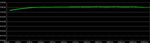
I moved all the bands down in frequency and put a 1uf cap instead of the 100n.
Now i'm getting a pretty dern flat reponse (see attached image) and the low end rolloff is acceptable for me.
I tried futzing around to get a higher Q ratio, but never arrived. If i can nail this (or find that i can't fix it) then it's time to order up some parts!
Suggestions on increasing the Q anyone?!
Opcom - go for it! I'm glad to hear you're giving it a shot.
Attachments
Here you go:
An externally hosted image should be here but it was not working when we last tested it.
Very cool! So, R5 can be replaced by a pot to change the frequency, right?
Also, R3 could be a pot to adjust the Q, correct?
Finally, any idea which frequencies C1 and C2 would create here? I am trying to follow the math in Geofex's site and am getting so lost. Any good reference for the frequency ranges possible with varying values of C1 and C2?
And this schematic is only one band.. Additional bands can be added in parallel to P1, right?
- Status
- This old topic is closed. If you want to reopen this topic, contact a moderator using the "Report Post" button.
- Home
- Amplifiers
- Tubes / Valves
- Fully Parametric Tube EQ (with gyrators)