thanks paffi for the quick reply ,let me perfect on designing high speed, Low EMI PCB . hopefully i,ll design a custom board for discreet ucd i found it sounding the best except layout issues.
These schematics seem good, however overcurrent protection is not quite fast, and I pull out of my hair seeing m for Mega and mk for micro. But still good candidates.
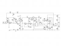
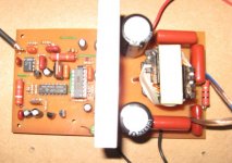
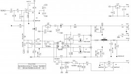
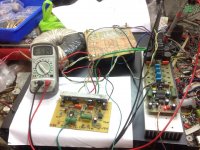
hi all full bridge using tl494 and dual ir2110. it seems to work well without issues imagine it has no feedback reference class d ถูกฯ(เพื่อการศึกษา) .
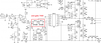
but i think i will make this one with lm311+74ac00+ir2110 + irfb4227 because it uses post and pre feedback i think it will be easy on layout and noise will be reduced . unlike ucd which is complicated to come up with a perfect silent layout without interference when multi-channel installed using one casing
but i think i will make this one with lm311+74ac00+ir2110 + irfb4227 because it uses post and pre feedback i think it will be easy on layout and noise will be reduced . unlike ucd which is complicated to come up with a perfect silent layout without interference when multi-channel installed using one casing
Attachments
-
 Class D Amp with LM566,LM393 and 2XIRF530 - Page 24 - diyAudio Mackie SRM450.JPG51.3 KB · Views: 1,322
 -
Class D 900 watts rms - Page 13 - forosdeelectronica.com fullbridge tl494.zip905.1 KB · Views: 506
-
 Class D 900 watts rms - Page 13 - forosdeelectronica.com 11ux07a.jpg92.3 KB · Views: 1,199
 -
 Class D 900 watts rms - Page 13 - forosdeelectronica.com 2el5xe9.jpg88 KB · Views: 1,276
 -
 Class D 900 watts rms - Page 13 - forosdeelectronica.com 2vtbdjp.jpg86.9 KB · Views: 1,298
 -
 Class D 900 watts rms - Page 11 - forosdeelectronica.com class d is the (education) ZRY8Jq.png136.2 KB · Views: 1,320
 -
900W.zip971.1 KB · Views: 424
-
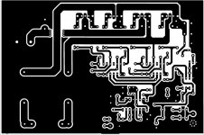
 classed900wfoto2.jpg52.8 KB · Views: 432
 -
 classed900wrms.jpg50.6 KB · Views: 435
 -
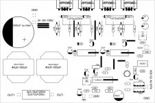
 classe d 900w.jpg164.5 KB · Views: 575
instead of doing full bridge this below design in class d to achieve high power .
the class d with class h super drive. the link >>> have fun all http://www.diyaudio.com/forums/class-d/226812-my-class-d-amp-69.html#post4968835
the class d with class h super drive. the link >>> have fun all http://www.diyaudio.com/forums/class-d/226812-my-class-d-amp-69.html#post4968835
Attachments
thanks paffi for the quick reply ,let me perfect on designing high speed, Low EMI PCB . hopefully i,ll design a custom board for discreet ucd i found it sounding the best except layout issues.
See that the good ones are discrete versions?, I have a discrete from the internet with some changes and faster transistors who do nicely, not a kilowatts version tough..
Nice thread.
kees
Kartino congratúlate you
Kartino congratulate you, for your design, I did it and works very well, regarding the "criticism of slow response to current limit" because I think you are correct, since mosfets support some microseconds with much more current ... .... the important thing is actually the audio quality, although I repeat there are people who only pass by criticizing, but they do not contribute anything .... greetings
Do you really want to tell what I talk about??? Trust me (or don't trust, just read again), I talked explicitely about short circuit. But you have only 1 circuit for both purpose.
At least you test it this way. But nobody can assure it is really momentary. It can happen any time, any duration and at any signal voltage. Short circuit in real life is not intentional. You can not control it.
Short circuit is PASSIVE. The amp is what provides energy.
Yes it is not fixed. I calculated the fastest possible reaction time what is already too high. But it can be slower. Do you think I ought have to calculate the slower one?
.
It is not a preference. I don't care wether you like sparks or not. It is an indicator of short circuit current.
No temperature rise either due to normal operation in the test, but in reality it can happen, therefore the test does not represent worst case. Not worst case also because of other reasons:
- natural variance of parts
- variable signal
And these are the smaller problems. The bigger is that you don't offer the real circuit you tested, only a theoretical schematic without exact part numbers and layout. Your design is on the borderline of safe operation. Any deviance from your unpublished building and testing habits can push it to the burning side.
This is my "secret": If I write current, then I mean current. Nobody cares how you limited voltage when the test is about a "short" circuit, and high currents, not about voltages.
And I mentioned many times an important test without any reply: short your single ended discrete amps with a piece of long and thick wire, without signal, and measure supply voltage!
Only the last one?
Kartino congratulate you, for your design, I did it and works very well, regarding the "criticism of slow response to current limit" because I think you are correct, since mosfets support some microseconds with much more current ... .... the important thing is actually the audio quality, although I repeat there are people who only pass by criticizing, but they do not contribute anything .... greetings
Rise and falltime is the most important part of class D, multi pole filters in a UCD second.
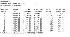
I did get 0.012% with 95 volts peak peak 8 ohms in 24 db octave bessel low pass.
I do use very fast opamp and parts in power comparator. however mje340 is not that fast
video transistors use here?.
I did get 0.012% with 95 volts peak peak 8 ohms in 24 db octave bessel low pass.
I do use very fast opamp and parts in power comparator. however mje340 is not that fast
video transistors use here?.
Attachments
Last edited:
Rise and falltime is the most important part of class D, multi pole filters in a UCD second.
I did get 0.012% with 95 volts peak peak 8 ohms in 24 db octave bessel low pass.
I do use very fast opamp and parts in power comparator. however mje340 is not that fast
video transistors use here?.
hi kees52 . please post a clear schematic and have you ever tried the amp in real life at +/-90vdc with 4ohm load??
I did get 0.012% with 95 volts peak peak 8 ohms
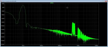
try to check mosfet's current waveform, or simply add mosfet's PD to see how hot they should be plot

try to check mosfet's current waveform, or simply add mosfet's PD to see how hot they should be plot
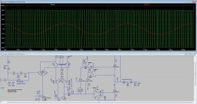
Waveform is the better way, because I do not now all about ltspice, this program still has suprises I do not now.
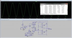
But here are some plots, I do now in real live things are always different, I do need to build it some day and see what happens, this is a power comparator who is very fast, in the nanoseconds, it is a excisting schematic from the internet, I have still not yet get a gate driver working in ltspice, but want to try that some dat day, special because the pcb is much easy to maken, and less parasitic inductances or capacitance, the golden idea for low distortion is very high speed and small dead times.
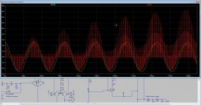
I did discover just that when there is no audio signal, the amp do not oscillate, if I put like 10 mv on it than it starts oscillate, this is not what has to be I think, it has to oscillate also without signal, but maybe a small signal do start it and then it keeps oscillating.
For clarity, mine low pass is a bessel type, because these have liniair fase en in 24 dB octave it looks like she do well. The amp has not feedback from speaker output.
I have change the comparator drives, also for test, but much difference I did not see, but can better manage the dead times with totem drivers.
These days I did see there are nice gate drivers, so good model for that I do like, who works afcourse.
I have ordered parts for mine circlotron, so I go do there first, the class D is afcourse a interesting topic, I do hear these can sound very good. Even better then analog ones
But tips from the specialists here is always interesting to take in considering. Ahh afcouse I did see here that diodes are used for signal clipping for overdrive protection, does that work nice?
some small resistors in serie with them give some kind of soft clipping and is more friendly..
Attachments
Last edited:
kees52, zero dead time it's problem in the real world with real 200V mosfets. BTW, FMMT591 has no gain at the current higher than 1A-1.5A, so where is the reason do not use 1A IC driver 20597/2092 etc? Yes, 50 cents of cost difference")
The original power comparator do use this setup, costs are not a issue but what I did was just some curiosity of this quite interesting technologie.
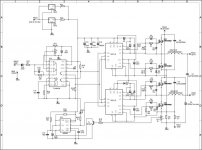
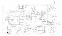
The dead time can be adjusted in the driver section like in schematic below, and the tekst picture do say that the D amps has getting growing up to very goog amplifiers, distortion is more spread also, that is nice.
Attachments

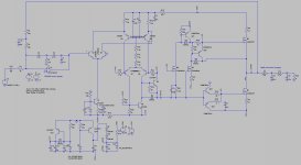
This is the power comparator and the output mosfets, trench mosfets.
Not mine own design but do try manage the feedback system and use bessel functions in low pass to get lower distortions.
But need real live build afcouse to get all the things done and now how it does,
cass D has quite complicated poles to reduce distortions, it has to be done manuallly, maybe big cap trimmers or such help...
good luck all, first mine present project.
regards
Attachments
This is the power comparator and the output mosfets, trench mosfets.
Not mine own design but do try manage the feedback system and use bessel functions in low pass to get lower distortions.
But need real live build afcouse to get all the things done and now how it does,
cass D has quite complicated poles to reduce distortions, it has to be done manuallly, maybe big cap trimmers or such help...
good luck all, first mine present project.
regards
hi kees . can your amp support a 2ohm load with a +/-85vlts with single pair of irfb4227 ?
hi kees . can your amp support a 2ohm load with a +/-85vlts with single pair of irfb4227 ?
I have even try 2 x 150 volts. but get uge amps on 4 ohm, and afcouse, the transistors need corrected that way.
This amp is not ment for thousends of watts, what I did try is to get high end, the idea of some people with other drivers for the mosfets are a good idea, I do not now how fast is a mosfet driver ic where dead band is included, for low distortion a multipole input feedback system is needed, however I did try the bessel as a low pas, with 24 dB but seems that the demodulation of the auio is lower with a given pwm swing.
I go look at it for you, 2 ohms can, but need some recalculations for output filter who do change.
speed and just more speed is the key for low distortion and a very liniair carrier, there are much thang about this on the internet, but the golden key is stil not yet found, al are the UCD designs very nice already and is a self oscilating design quite liniair of his own. because of bessel output filter who is fase liniair I do not use post feedback but only pre, the impedance is higher but the bass coils are low impedance , I think this can give a very dynamic sound.
You be aware that the irfb4227 has 4600 pf gate capacitance, needs some amps to distcharge? do not now that a bootstrap can do this, need higher cap then.
regards
Last edited:
kees52, zero dead time it's problem in the real world with real 200V mosfets. BTW, FMMT591 has no gain at the current higher than 1A-1.5A, so where is the reason do not use 1A IC driver 20597/2092 etc? Yes, 50 cents of cost difference
I go try mosfet drivers, because that way dead zone is much better manageble, I however have not good ltspcie models of them.
A good low pass designer is also welcome, also with bessel functions.
Then later I go try that what is coming out. I need more then 1.5 amp driver current, 3 fold maybe. the mje 15031 is a high speed 8 amp bjt capable of 10 Mhz bandwidth.
The LTC4446 is a nice one, but needs separate dead time generator, but this is easy with some mos ic and one resistor and one cap, (each side) ordered also 10 ir2110 chips.
regards
Last edited:
kees52, yes, it is a good idea, going forward step by step. You can add a buffer on BJT follower after 20957 and get >3A. I like zetex/diodes BJT pair in the sot-23-6 5A pulse zxtc2045e6ta, very compact and reliable, $.2/pcs. Or look at this tiny monster https://www.diodes.com/assets/Datasheets/ZXTC6718MC.pdf , gain 180 at 6A ))
Is CE voltage not a little to low for a high power class d driver? bootstrap give voltage above mosfet rails. it is indeed a big monster in a small package, nice low saturation resistance.
- Home
- Amplifiers
- Class D
- Fullbridge Class D PA ultra high power