That's a shaded line array. Look up the CBT papers from Keele instead. He uses half an array with the mirror from the floor acting as the other half.
This won't be comparable to what we are doing. This one from JBL is meant for PA and not using the floor. As such it won't act as our arrays, sorry.
(By design it is using the same principle as Keele's CBT but this one does not "need" the floor. Our arrays do benefit from it as do the Parts express CBT's)
Last edited:
Because a shaded array (we're talking shading of the bottom elements here) won't act as a taller array (together with it's floor mirror). This one is for different purposes.We are talking 500 Hz here. Wavelength 60cm. So the wavelength spans multiple elements i both systems. How can the difference be huge?
Just look up the papers and start reading and digesting the why. You're still in the: 'jump to conclusions' mode. An open mind would help.
")
As of the DRC comment:
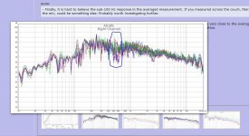
Inside the listening window, the sharp notch created by the back wall varies inside 500 to 650 Hz. That is 30 % span in frequency for a sharp notch summing filter. (Sum of direct and reflected sound)
The time spike will have to move accordingly to generate ONE dip between 500 and 650 Hz.
Even if DRC is time correcting it is still convolution so can only be perfect in one place in space.
But then again, maybe DRC is smarter than me
Anyways as I am sure DRC is not created with arrays in mind, I am impressed if it works flawlessly with one.
Attachments
Because a shaded array (we're talking shading of the bottom elements here) won't act as a taller array (together with it's floor mirror). This one is for different purposes.
Just look up the papers and start reading and digesting the why. You're still in the: 'jump to conclusions' mode. An open mind would help.
So its the array to the left that is reflecting on the floor at 500 Hz?
http://www.xlrtechs.com/dbkeele.com/images/Card Back Large.png
Nope, wrong again. I did say look at the CBT array, didn't I? The left graph isn't representative of a floor to ceiling array. Reading the paper should make that clear.So its the array to the left that is reflecting on the floor at 500 Hz?
http://www.xlrtechs.com/dbkeele.com/images/Card Back Large.png
The right array graph is formed by a Keele CBT and its floor mirror.
On the left is a short unshaded array. Ignore that. Not relevant to get you up to speed on array behaviour at all.
I see the parabola effect behind the speaker on the CBT though. So the back reflection is not so strong mid array with a straight array. (Still strong enough to make the dip shown a few posts back)
See there are 3 SPL maximas along the array at 500 Hz. So adjusting the height may reduce the reflection somewhat?
See there are 3 SPL maximas along the array at 500 Hz. So adjusting the height may reduce the reflection somewhat?
As of the DRC comment:
Inside the listening window, the sharp notch created by the back wall varies inside 500 to 650 Hz. That is 30 % span in frequency for a sharp notch summing filter. (Sum of direct and reflected sound)
The time spike will have to move accordingly to generate ONE dip between 500 and 650 Hz.
Even if DRC is time correcting it is still convolution so can only be perfect in one place in space.
But then again, maybe DRC is smarter than me
Anyways as I am sure DRC is not created with arrays in mind, I am impressed if it works flawlessly with one.
Why do you think I worked for more than half a year optimizing settings in my own DRC template. Other than that, its still math whats being done here and why should it not apply to arrays? I'm close to giving up here. Do you want to learn something or in it for the argument....
A DRC discussion is completely separate from the arguments you're trying to make.
Even with that wall reflection (which is absorbed in my own room) your assumptions are wrong. It will be valid for every position that has that reflection in that same time span. You do remember this being the result of using an average of 9 measurements, right? I'm thinking you don't get what that averaging does. Its very similar to what the arrays are doing with their multiple full range sources.
Please don't jump to conclusions anymore. Read up on the theory first. Lots of sources with conflicting data but they all agree on that floor reflection behaviour. And for good reasons.
And he forgot all about the floor and ceiling. Isn't that funny? He did remember to include the floor for his own baby, the CBT.It's 2 meter high and 100 point sources.
All I see here is more guess work from you.I see the parabola effect behind the speaker on the CBT though. So the back reflection is not so strong mid array with a straight array. (Still strong enough to make the dip shown a few posts back)
See there are 3 SPL maximas along the array at 500 Hz. So adjusting the height may reduce the reflection somewhat?
All I see here is more guess work from you.
So ists no SPL max and minimums along the length of an 2 meter array at 65cn wavelength?
Ask Keele about that.And every floors and ceiliings has the same reflective index of one at all frequencies.
You keep forgetting the drivers are closely packed in the array and end just above the floor. Largely different from a single woofer above that same floor. Now go apply Keele's logic to that array and add a floor and ceiling reflection. What happens? Every paper on floor standing arrays covers this. Can you find the answer?
I do hope we're still talking about the seemingly absence of the floor reflection in fluid's measurements as you seem to keep bringing up the wall reflection in replies.
Based on that left graph again? Sigh... what was missing from that picture? What would it look like if the reflections from floor and ceiling were included?So ists no SPL max and minimums along the length of an 2 meter array at 65cn wavelength?
Sorry, I lost you.
A floor acting as an prfect mirror must not absorb the sound. But in many cases in domnestic homes we have carpets or thin wood/plastic over a cavity or insulating material. Concrete is much more normal where most arrays are used. So Keeles assumption is good.
All I can conclude from the measurements in other posts is that floor reflections are hidden in the floor reflection. Hidden is not the same as non existent. (But in this case I don't think floor reflection matter as the other reflexion dominates)
Again, read Keele's papers. Then apply the same logic to our arrays. Where the floor reflection would act up is less than the distance between the lower elements and the floor. I guess I'm missing one TC9 max at the bottom. I don't think fluid's marvelous build is any different.wesayso: I understand your argument if:
*The array are real floor to ceiiling with less than one element gap between element and bounadary
*The floor and ceilling is made of untreated concret. Or other stone hard and decimeters thick material.
I also made several measurements with an absorbing panel above the array to see if it would make a difference. Guess the outcome of that experiment.
Last edited:
Never mind. You never "got me" anyway.Sorry, I lost you.
A floor acting as an prfect mirror must not absorb the sound. But in many cases in domnestic homes we have carpets or thin wood/plastic over a cavity or insulating material. Concrete is much more normal where most arrays are used. So Keeles assumption is good.
All I can conclude from the measurements in other posts is that floor reflections are hidden in the floor reflection. Hidden is not the same as non existent. (But in this case I don't think floor reflection matter as the other reflexion dominates)
Keele's CBT line is ment to perform in regular homes. The JBL variant isn't.
But... this is the first time you're comming close to the right answer. I'll leave it at that.
Goodnight!
- Home
- Loudspeakers
- Full Range
- Full Range TC9 Line Array CNC Cabinet