Hi all.
With a change of R & C values, could this circuit provide BOOST in the treble, rather than cutting the highs, for use with a line array(where comb filtering already reduces the highs)?
Also, could the low frequency filter be tailored for B.S.C.? If so
this sure would be nice for a line array.
Thanks for any suggestions here.
-C
Last edited by a moderator:


General question: Could this be used in conjunction with the 6-24 active crossover in the following manner:
Preamp ---> FR EQ ---> Active crossover ---> Power amps
It seems this would duplicate the functionality of the LX-mini/ACN but in a format that is more easily adjustable.
Preamp ---> FR EQ ---> Active crossover ---> Power amps
It seems this would duplicate the functionality of the LX-mini/ACN but in a format that is more easily adjustable.
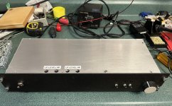
I have done exactly what you are asking in a just finished build. Both EQ and 6-24 in same chassis with the option of using the 6-24 with either its own input or the output of the EQ board as input. I also have a bypass switch for the EQ and separate mute switches for HP and LP 6-24 outputs. I also put in muting at power on/off as well. I have only had a chance to do basic tests so far. Planning on experimenting with Open baffle speakers so this was a nice first step to help out with that. Many thanks to Nelson Pass for the designs and circuit boards!


Attachments
Last edited:
Hello Faizal
On the left is a CLC RF filter board for the switching power supply input. On the right is a board holding the relays that do the switching of inputs and the bypass for the EQ. Because of the relays the power consumption is about 250ma at 24V. The switching supply I have is a 25w 1.04 amp capacity but it would not startup because of the capacitive load from the Crossover boards CrCrC filter . You can see a large green resistor at the input to the rf filter board. In order to get the PS to start up I had to convert the PS from CrCr filtering to RcRc by placing a 5ohm resistor in line with the 24v input. That reduced the inrush current to the point where the switching supply starts up without issues. I then bypassed the first 10 ohm resistor on the crossover board to minimize the DC voltage drop.
You can use the eq and crossover independently or in series with this setup and bypass the eq to A/B the results. You can mute either crossover output independently for testing or listening purposes.
Thanks Mr Pass. I'll get one.I am happy to present you with a project that I did 5 years ago which has served me well since.
- The Equalizer for Full Range Speakers Essentials Kit is available in the diyAudio Store.

In the article on page 3 it's mentioned we can change the high frequency
attinuation by changing the value of R5 between 33k and 123K . But what
about P1 ? could it be that 33k to 123k figure for R5 was including the resistance
or P1. If so and I need the full 4 db attinuation couldn't I simply eliminate P1 ?
attinuation by changing the value of R5 between 33k and 123K . But what
about P1 ? could it be that 33k to 123k figure for R5 was including the resistance
or P1. If so and I need the full 4 db attinuation couldn't I simply eliminate P1 ?
Is there a way this circuit (kit) can be tailored to give a boost at high frequencies? I know, it's not what we'd normally want for full range drivers, but I have a need for something like this.
Ideally I would want a ramp-up starting around 3KHz and reaching 1.0 - 1.5 dB at 20kHz.
Try as I may, the best I could manage was a flat line, but no boost. See the values and plot below.

Ideally I would want a ramp-up starting around 3KHz and reaching 1.0 - 1.5 dB at 20kHz.
Try as I may, the best I could manage was a flat line, but no boost. See the values and plot below.
Last edited by a moderator:
There is no gain, so no amplification.
I'm referring to a resistor and capacitor in parallel in series with the signal. This is also used in speaker crossover filters to increase the high frequency response.
The resistor will attenuate all frequencies, but the capacitor bypassing the resistor will allow the higher frequencies to pass through. The higher the frequency, the greater the magnitude. Try different values of resistance and capacitance.
- Home
- Amplifiers
- Pass Labs
- Full Range EQ