Thks Nanoloop and many others...
As all marketing text of FDA, devil is in the details.
Thus also did crazy search web more info D8 & V200 components specs.
Your thoughts helped to affirming the search conclusion on quantitative details.
FDA not entirely depend on specs - currently for musical purpose Open loop seems better over closed loop
V200's TAS5614LA has higher output, while D8's obsoleted STA328 lower power is still more than sufficient for me. V200 wifi DLNA/Airplay spotify casting seems a strong push-factor; D8 carefully picked various components, chipset make it high quality in SQ, USB, S/Pdif, all-rounder performance makes great usability as an integrated FDA.
Ordered D8, is on travel now.
Next thing... would be modding to improve D8 internal power supply. has globulegl got a D8, done any study changes ? anyone has experience to share?
Thks all - it is real great to have you all on DIY community.
Last edited:
I'll stick to that if you recalculate a PCM stream to change it's sampling frequency, the jitter the converted analog signal will be contaminated with stems from the "new" clock + rounding errors from the necessary interpolation of the new samples. As no *real* clock has been involved during the recalculation of samples, no jitter can be introduced as the clock aspects (old as well as new Fs). Jitter is defined as: the deviation from the nominal, ideal clock tick occasion.
As per if it introduce or reject jitter on the ingress side - it can't do any of these. Period. I agree to the notion that ASCR is indeed in a way a DA conversion and as we all now, once you start turning a digital word into the representation of an analog value, the quality of the clock is what governs the jitter. Now - in the ASCR case, there is no analog signal level actually created but rather a new representation of a level in terms of a new PCM sample. The new sample is associated with a new Fs and - here is the thing - both of the 2 involved samples has been calculated using it's nominal Fs, not an actual clock - everything has been going on in software - if it wasn't for the case that these circuits are real-time, this could be done off line during 10minutes which makes it obvious that none whatsoever clock has been involved in the calculation of the new samples - and again - no jitter can be introduced or removed for that matter.
I would be very surprised of Bruno would have any other position on this. The example linked involves a pluralis of digital streams to be mixed, all generated by their own clock and despite that they all say "I do Fs = 96", they actually differ a bit - and in the discussed situation this really matter. But in the "replay 1 PCM stream", which is discussed hare, this is of no concern. Just treat all incoming samples to have the nominal Fs as declared and decide your out Fs. The jitter on the incoming side is the one introduced at the recording or other **** happening in mastering phase - this can never be removed. The jitter relevant at D/A conversion will be determined by the clock used by the DA. The new rate converted stream will contain round errors from the calculation of new samples - yes - but to call these "jitter" error is in my book wrong as no actual clocks have been involved.
If indeed ASCR circuits used in DA converters do make use of "rate estimators" then they are the wrong tool for the job. There is no need for any estimation if you come with one PCM stream that is declared to be 44,1 and you want to up-rate it to 96. Again s/pdif is special - but it would be idiotic to use a continuously s/pdif extracted clock to calculate the Fs for the incoming stream.
As it stands, my view is that ASCR seem to probably introduce jitter rather than the other way around - at least if it does continuous rate estimation during the process. Why estimate when known? Again - I can see an other situation in a multi sources case.
But maybe its terminology. Jitter is a x-axis fault. Sample calculation rounding is an y-axis fault. The x.y position is the pudding.
//
Why estimate when known?
In what sense is the incoming fs known? ASRCs have to measure it, all measurements have finite resolution, depending on their sample clock rate and the number of averages they choose to make.
As regards being 'the wrong tool for the job' your suggested 'solution' looks to be SRC (when there's a fixed ratio between the input and output fs). Of course where possible, SRC should be used in preference to ASRC but its not always possible.
Last edited:
If we want to replay a CD and have the output not at 44k1 (for the sake of argument let's say at 96k) then if we put the sample-rate converter inside the CD player we still need to have a clock running at 96kHz. We could arrange it to be generated from the 44k1 master clock via a PLL but then we'll have the PLL's jitter on the 96k clock. In such a case we could use a mere SRC with a fixed conversion ratio, no need for any ratio estimator.
Thks Nanoloop and many others...
As all marketing text of FDA, devil is in the details.
Thus also did crazy search web more info D8 & V200 components specs.
Your thoughts helped to affirming the search conclusion on quantitative details.
FDA not entirely depend on specs - currently for musical purpose Open loop seems better over closed loop
V200's TAS5614LA has higher output, while D8's obsoleted STA328 lower power is still more than sufficient for me. V200 wifi DLNA/Airplay spotify casting seems a strong push-factor; D8 carefully picked various components, chipset make it high quality in SQ, USB, S/Pdif, all-rounder performance makes great usability as an integrated FDA.
Ordered D8, is on travel now.
Next thing... would be modding to improve D8 internal power supply. has globulegl got a D8, done any study changes ? anyone has experience to share?
Thks all - it is real great to have you all on DIY community.
Enjoy it! I love hacking gear but I've learnt not to be too quick to start -
I leave it running continuously for a few days while making plans for upgrades, then spend as many hours as possible listening so I know its character beforehand and what needs "fixing" - more plans ;-) For sure, power is almost always a good start but for me it's worth knowing the gear well so I can appreciate the improvements from upgrades.
If we want to replay a CD and have the output not at 44k1 (for the sake of argument let's say at 96k) then if we put the sample-rate converter inside the CD player we still need to have a clock running at 96kHz. We could arrange it to be generated from the 44k1 master clock via a PLL but then we'll have the PLL's jitter on the 96k clock. In such a case we could use a mere SRC with a fixed conversion ratio, no need for any ratio estimator.
This works in practice - use an ASRC to double the native sample rate so the ratio is a simple integer. From datasheets, this usually gives the best performance. I built a DAC to do this for CD - it uses AD1896 and Crystek CCHD957 22.576MHz clock to turn 44.1 into 88.2 ahead of a WM8741 DAC.
No system is jitter free so what matters is the level when it becomes inaudible - scroll down to the bottom of this article for a perspective on that. NwAvGuy: Jitter Does it Matter?
It's also worth noting that the STA326 has a resampler - the datasheet says it resamples to 96kHz and uses 24 to 28 bits. It seems to do this very well and I can't help wondering what input sample rate input would make the best of this chip. Sadly, the YJ won't let me feed it anything except 44.1 and 48kHz so I'm using 48 - I don't fully understand some parts of the datasheet but it seems to me that the integer thing works for this too.
Last edited:
On another post, Audeo modded D8; he put back missing parts of STA326 reference design (towards tail-end output to speakers), some snubbers. Not sure is that helps ~ for protection or for SQ?
However it dint remove hiss, but after adding 15uH to +Vin of 5V smps regulator noise is removed.
I am thinking instead of the 15uH, replace 5V smps a LDO 7805 40uV noise~60dB PSRR (may work if current drawn not huge - more heat), does any difference for SQ, as FDA also had ADC, and analog headphone amp?
Last edited:
On another post, Audeo modded D8; he put back missing parts of STA326 reference design (towards tail-end output to speakers), some snubbers. Not sure is that helps ~ for protection or for SQ?
However it didnt remove hiss, but after adding 15uH to +Vin of 5V smps regulator noise is removed.
I am thinking instead of the 15uH, replace 5V smps a LDO 7805 (may work if current drawn not huge - more heat), does any difference for SQ, FDA also had ADC, and analog headphone amp?
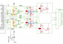
I fitted a "missing snubber" on my YJ too - the ones circled in yellow - it is a MHz filter and I didn't hear any difference. They were the only missing parts compared to what's described in the datasheet.
An externally hosted image should be here but it was not working when we last tested it.
Audeo seems to be saying there are more snubber parts missing on the D8 ? Red parts are missing so it seems there is more to be gained from "fixing" that.
http://www.diyaudio.com/forums/class-d/299580-fda-alientek-d8.html#post5164633
My amp design used an LM2575 to drop the input voltage to 5V and this is followed by an AMS1117 3.3V reg for the digital section. I expect the D8 is more complex?
To replace the LM2575, I ended up creating two power inputs: 12V and 30V, so an independent 12V can feed the digital section which is now 7809 > 7805 > TPS7A85. Simply replacing the LM2575 with even 2 or 3 linear regulators meant they each get too hot - over 80degC with a small heatsink. If I was doing this over, I might try a capacitance multiplier after the LM2575 and replace the AMS1117 (100uV noise 1V dropout) with a low noise low dropout (10uV or less, 500mV dropout) regulator capable of 250mA from less than 4V. The cap multiplier will need a high B and high bandwidth NPN transistor to be effective.
The most noticeable effect of better power is to make the YJ 2.0 amp fully silent with no signal lock. The YJ 2.1 has obvious noise listening from 30cm and closer and the noise is actually similar with either a linear supply or smps. I blame the LM2575.
Overall, better power has improved the sound quality, but without back-to-back listening tests or quantitative testing, I can't say more.
Last edited:
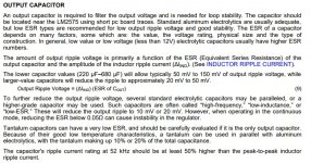
According to its DS, LM2575 has output ripple (52kHz typically) of around 1% of the output voltage. Hence 50mV for a 5V supply.
My Popu digital amp has an ADC which is fed from a buck reg (might even be an LM2575) and the dynamics sucked big-time on the analog input until I installed an LC filter on its power rail.
My Popu digital amp has an ADC which is fed from a buck reg (might even be an LM2575) and the dynamics sucked big-time on the analog input until I installed an LC filter on its power rail.
According to its DS, LM2575 has output ripple (52kHz typically) of around 1% of the output voltage. Hence 50mV for a 5V supply.
My Popu digital amp has an ADC which is fed from a buck reg (might even be an LM2575) and the dynamics sucked big-time on the analog input until I installed an LC filter on its power rail.
The datasheet says noise can be reduced by using >680uF on the output (min ESR is 0.05R) and that noise can be further reduced by a factor of 10 with a second LC filter of 20 μH & 100 μF. It's still going to be noisy though eh. But the efficiency means no heat issues so ...

Are talking about a second LC filter? I think that would have a very high Q if the cap was much over 10uF? So it would cause ringing? 1mH and say 2uF with a load of 3.3V @ 200mA - would give about 45dB and not ring? That would take 50mV down to 300uV. Doable!?! The largest I have is 100uH on hand tho.
Last edited:
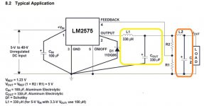
from LM2575 datasheet - extracted the description & a schematic -
the recommend 1st pair of LC is now highlighted in yellow box.
Abraxalito, I guess you are regarding 1st pair of L and C (1mH L and a low ESR 'lytic (Nichicon HZ) right? what L C value is approriate?
Nanoloop, the 2nd pair LC (20 μH & 100 μF) modded in orange box - is it correct?
the recommend 1st pair of LC is now highlighted in yellow box.
Abraxalito, I guess you are regarding 1st pair of L and C (1mH L and a low ESR 'lytic (Nichicon HZ) right? what L C value is approriate?
Nanoloop, the 2nd pair LC (20 μH & 100 μF) modded in orange box - is it correct?
Attachments
Last edited:
Anyone can make a guess what are functions/impact of the remaining red miss parts in these 4 areas (as pointed by Red arrows) - D8 removed them & had the blueline shorted to ground.
I intend to restore the snubber filters in yellow box, not sure if it is worthwhile to follow-thru the remaining 4 red areas
I intend to restore the snubber filters in yellow box, not sure if it is worthwhile to follow-thru the remaining 4 red areas
Attachments
from LM2575 datasheet - extracted the description & a schematic -
the recommend 1st pair of LC is now highlighted in yellow box.
Abraxalito, I guess you are regarding 1st pair of L and C (1mH L and a low ESR 'lytic (Nichicon HZ) right? what L C value is approriate?
Nanoloop, the 2nd pair LC (20 μH & 100 μF) modded in orange box - is it correct?
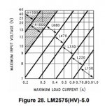
Datasheet Fig 28 suggests the output inductor should be either 33uH or 47uH for the load (about 200mA in my YJ, maybe higher in the D8). My YJ has 33uH. This value is dependant on the load and the graph has shaded out 1mH - I assume that's because the load would need to be very light not to cause oscillations.
The output cap advice is as large as possible but with an ESR no less than 0.05 ohms. For a low ESR cap like Panasonic FM, that means an 8x11.5mm size which is at best a 560uF 6.3V cap. For Panasonic FC it can be a 1500uF 6.3V 10x20 or 12.5x15.
The second filter looks correct - no specific details given.
Bear in mind that this will give, at best, about 1mV of ripple/noise at 50kHz. This is still very noisy.
Last edited:
Anyone can make a guess what are functions/impact of the remaining red miss parts in these 4 areas (as pointed by Red arrows) - D8 removed them & had the blueline shorted to ground.
I intend to restore the snubber filters in yellow box, not sure if it is worthwhile to follow-thru the remaining 4 red areas
All of those parts (everything after the inductors) make up the output filter which removes the digital "noise" from the analogue signal. You can Google "BD output filters" and read the pdfs from TI to find out more. TI also do a spreadsheet that has an output filter calculator if you want to design your own, or model the D8 design. You can download it for free. It's very handy for getting the filter to match the speakers. LCFILTER-CALC-TOOL Class-D LC Filter Designer | TI.com
To help my amateur-level in understanding:
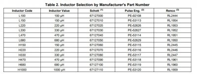
Referencing fig.28 & Table 2 for LC -
"This value is dependant on the load and the graph has shaded out 1mH。
Using YJ 5V@200ma as example, either 33uH or 47uH"
33uH/47uH correspond to less than 100uH (frm Table 2 that would be inductor code L100), cross-ref to fig 28, meaning bottom-right corner of low input voltage + high load current?
or for YJ, Vin cld it be 12V, to 5V@200ma, gives something like L680 ie. 680uH?
another question is: say nominal load 200ma, but let say we pick inductor for 400ma (factor max load case). Using inductor for 400ma, what impact when the load at 200ma?
Attachments
I would not recommend to replace the DC-DC converter in Alientek D8 with this one, because the one in D8 seems to be MP2451 which uses 2 MHz oscillator, and 2 MHz is much easier to filter out than a few dozen kHz.from LM2575 datasheet - extracted the description & a schematic -
the recommend 1st pair of LC is now highlighted in yellow box.
So, if someone who's good with transistors can pass an eye over this...
I plan to use a BC337 NPN as a pass transistor in a capacitance multiplier. It has a min DC gain of 100, 100Mhz bandwidth, 800mA limit. The load is a 3.3V regulator which uses up to 11mA and the actual load which is around 200mA, so let's say 300mA. All good so far?
To bias the base from the collector, I need at least 300ma/100 = 3mA. Let's say 5mA. The voltage drop would be 0.7V so, the resistor across collector and base is 0.7/0.005 = 140R. Still good?
To create a low pass filter I need C = 1/6.28*140*F. To avoid any possible issues with a slow start (?), make F ~ 25Hz so C should be 47uF.
This filter will give -66dB at 50Khz, which will, in theory, turn 1mV into 0.5uV, but this would be lower than the noise from the BC337 so this is where I get really stuck. How do I work out what the noise of the BC337 is? Little help? If the noise level is far higher, is it still necessary to use a large cap at the base? Or can I use bigger and not worry about the slow start?
Thanks for any help!
Last edited:
- Status
- This old topic is closed. If you want to reopen this topic, contact a moderator using the "Report Post" button.
- Home
- Amplifiers
- Class D
- Full digital amplifier with chip STA326