"frequency change"? As in a pitch shift?
That's probably a more accurate description. For example, sliding up a fretboard on a guitar.
Is AMB's schematics enough to produce I2S with all sampling rates and feed it to the ADAU1701?
I believe sampling rate is irrespective of physical hardware. If I remember right the important thing to set was the program length in sigmastudio. E.g. if you have a 48khz source the program length is 1x (1024 instructions), at 96khz it would be 2x (512), and at 192khz it would be 4x (256).
With a 12.288mhz clock I believe that this would mean that 192khz would be running at 64*fs.
So far everything assumes that you're using a 12.288mhz clocks - which is what the FDSP classic uses. The way I have it wired to the classic is I bent the pins, and direct soldered them on the 3pin jumper for clock. This tied the xo's output to the adau's input, and also tied them both to the external clock on the main header. This configuration essentially excludes 44.1khz and higher frequency variants of 44.1khz.
The Z1 has two clock inputs, one for 44.1 master clock and another for 48khz. I tied them both together (and I believe that the firmware will not initialize if there's not 44.1khz clock).
To get both 44.1khz and 48khz and there higher bitrate variants, you'll need to have two master clocks. AMB's website has a schematic for the Gamma 1.5 which will give you an idea how he implements that switching:
He has a 24.576 and a 22.5792 XO. They're 4-pin XOs with an enable/disable pin. He's using a (U2) SN74LVC1G00DBV driven off of Z1 Pin-32 (MCLK_P48_N441) to flip between the clocks.
The other IC in that block is (U3) is functioning as a clock divider. That's because the audio-widget implementation is expecting a 12.288mhz / 11.2896 master clock. However many DACs will perform better with a higher frequency clock, so the DACs are on that board are clocked off the 24/22mhz clocks.
For the ADAU1701 - you can feed it a 12/11mhz master clock, or feed it the 24/22mhz clocks. If you feed it the higher frequency clocks you'll need to adjust the PLL_MODE0 and PLL_MODE1 pins, otherwise you'll end up overclocking the ADAU1701 (which may or may not work).
Hope that helps.
Thanks. I guess pavouk's site has the complete schematics that could work out of the box with FDSP:
http://www.pavouk.org/hw/audiosystem20/en_at32uc3a3256usbi2s.html#pcb
Thanks. I guess pavouk's site has the complete schematics that could work out of the box with FDSP:
http://www.pavouk.org/hw/audiosystem20/en_at32uc3a3256usbi2s.html#pcb
Yeah his schematic includes the clocks, clock switching, and clock divider functions onboard. That's a great link - thanks for sharing.
")
Thanks. I guess pavouk's site has the complete schematics that could work out of the box with FDSP:
http://www.pavouk.org/hw/audiosystem20/en_at32uc3a3256usbi2s.html#pcb
I sent the .brd file for that board to oshpark the other day.
Also ordered most of the parts from mouser.
Currently trying to get the software side working on my Linux pc. Not an expert, I learn as I go.
Atm, the sw doesn't compile/build all the way through, I'm trying to find the cause and hopefully fix it.
If unable to do so myself, I'll contact my cousin who works with Linux all day at his job.
Would be nice to have done it myself though.
I'll have atleast one of the PCB's over as I ordered 3pcs from osh. I went with the "double-thick-Cu-layers" 0.8mm PCB's.
Nice. Can't wait to hear about your experience with this. Are you doing to use a stencil for the solder paste or wing it? Or... drag solder?
Nice. Can't wait to hear about your experience with this. Are you doing to use a stencil for the solder paste or wing it? Or... drag solder?
Yes it's exciting to try this MCU-based solution
I have tried stencil once on QFN20 package, but I honestly prefer to apply solder paste manually, probably because I'm not that skilled at using stencils yet.
Hello,
I am just now building some freedsp classic master boards.
Did get my pcbsdone by dirtypcb, the dnagerousprototype pcb china company, maybe some of you might know.
I discovered a slight problem with the 12,x MHz oscillator on the PCB I think the bottom solder pads are not in the soldermask layer, eagle looks fine though, also the gerber files do look nice in the gerber online viewer.
So maybe this is an error in the library of eagle, I got no clue, just wanted you guys know, in case you got some similar plans, of letting manufacture in china, maybe they did something wrong, or maybe its already in the original eagle file, the vias for the oscillator seem less in diameter than the ones for the caps beside it.
Anyway, I did solder the oscillator a little above the pcb and one I decided to put underneath the PCB.
BUt I havent powered my PCBs on nor tried prgramming them yet, so I dont know if it works yet.
cheers, and thanks for putting up the project.
Hi all,
Where could I find the BOM for the SMD A rev A and the unbalance out 8x ?
Thanks,
Carlos
You would need to create BOM from schematics. SMD versions have ceramic smd capacitors in signal path which is not recommended practice due to distortion. Not sure why smd board was designed like that.
My Widget based FDSP board is almost finished
Looking good
Using the ADAU1701? I've looked into doing something similar myself, don't think I'm good enough at using EDA's yet though, but use a newer/more powerful/flexible DSP IC.
I have two fully populated FreeDSP Classic boards that I haven't gotten around to putting to use yet so...a project for when I'm more adept at using KiCad and more read up on DSP in general.
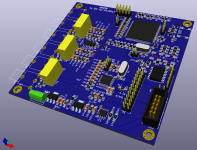
Here's the latest version, I added back Arduino Nano. Yes, it's ADAU1701. I am thinking about adding two more DACs, so that I can get 6 analog outputs from single ADAU1701.
Attachments
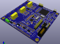
Here's the latest version, I added back Arduino Nano. Yes, it's ADAU1701. I am thinking about adding two more DACs, so that I can get 6 analog outputs from single ADAU1701.
I have to admit, you are way ahead of me (using an EDA etc)
What D/A's are you using?
I was thinking along the lines of ADAU1452, in fact I started a looong-term project using that in KiCad this morning.
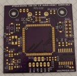
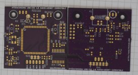
I got the Audio-Widget boards from oshpark today, surprisingly fast as I did opt for the 0.8mm, 2oz Cu option.
Attachments
I have to admit, you are way ahead of me (using an EDA etc)
What D/A's are you using?
I was thinking along the lines of ADAU1452, in fact I started a looong-term project using that in KiCad this morning.
I got the Audio-Widget boards from oshpark today, surprisingly fast as I did opt for the 0.8mm, 2oz Cu option.
Still no standalone DACs on board, just the ones inside ADAU1701. It's on a roadmap, but not sure if it will fit the 10x10cm pcb. It might be AD1955 or PCM1794.
- Home
- Source & Line
- Digital Line Level
- freeDSP - an open source 2-in 4-out digital crossover board