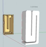
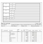
The first image should be a layout for ONE PAIR from a single sheet of Ply/MDF.
The second should be THREE(3) PAIR from a single sheet.
HAPPY CUTTING! Keep safe....
Thank you very much - that was very nice of you!
Beau
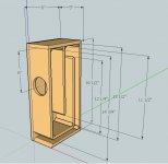
Optimized Plan
After tinkering with the design for a few, (and finding out that the Aura drivers are no longer available from Madisound)...I have Made a plan for the Dayton Dayton Audio ND91-4 drivers which are availible from Parts-Express for $28.65 (as of the time of this post). Quite a bit more expensive but worth the extra change. The new design followed a criteria which is optimized for build time, reduced complexity and budget. Just my take on a small DIY build anyway. Enjoy! Below is the link to download the Sketchup file.
After tinkering with the design for a few, (and finding out that the Aura drivers are no longer available from Madisound)...I have Made a plan for the Dayton Dayton Audio ND91-4 drivers which are availible from Parts-Express for $28.65 (as of the time of this post). Quite a bit more expensive but worth the extra change. The new design followed a criteria which is optimized for build time, reduced complexity and budget. Just my take on a small DIY build anyway. Enjoy! Below is the link to download the Sketchup file.
Attachments
Thank you.
As for the Aura's availability, I believe they are still availbale for $12.50 each.
The Madisound Speaker Store
As for the Aura's availability, I believe they are still availbale for $12.50 each.
The Madisound Speaker Store
Thanks for the all the info on this design. I'm very new to DIY speakers and the thought of a FR in a TL has intrigued me. Once I came across this thread, I had to build these boxes since I already have a pair of NS3-193-8A1's which were used in a Sprite Boombox.
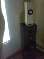
This was a quick and dirty build for a set of garage speakers. Wood, is from an old cabinet; I raided my wife's sewing closet for the stuffing; drivers were purchased when they were $12.50 (I'm kicking myself for not buying more at this price); including incidentals (speaker wire, nails, glue, sandpaper and Danish Oil) I'm in these for around $35 and a few hours of labor. I love em. I certainly don't have an ear, but I'm impressed these. At this point they need a little more love to minimize air leaks along the line. A gasket for the driver is definitely needed (mounting flange is slightly bowed) and a proper terminal (speaker wire is ran through a hole in the back and sealed with caulking which isn't holding up to my abuse).
Also my boxes ended up about 1/8" taller because of the thickness of wood used. I didn't compensate for this on the depth so the cross section of the line is slightly less.
Some Pics:
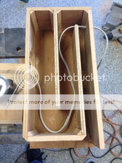
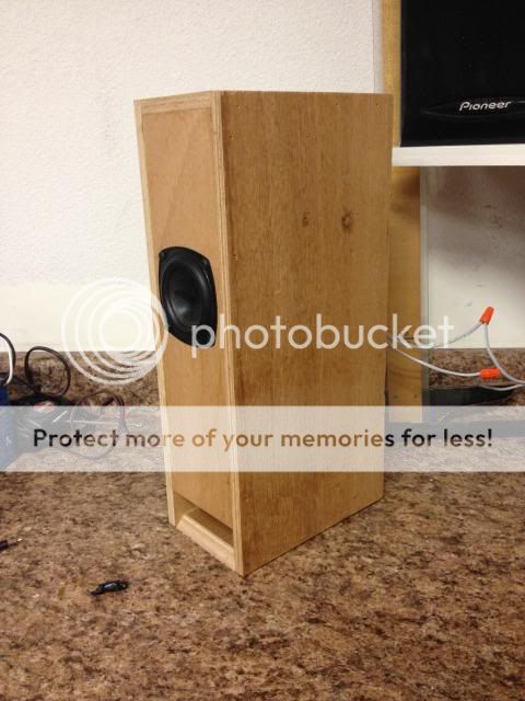
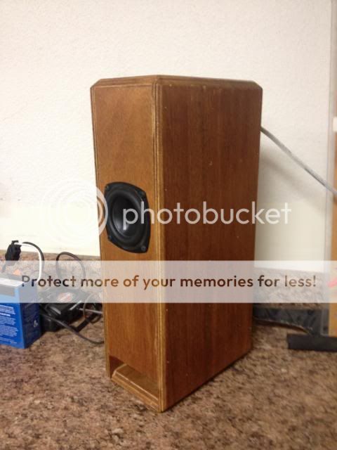


I cut and installed a gasket for the driver and I applied more caulk around the speaker wire. This cleaned up the sound and really brought out the highs. I hooked up Paul's filter (.90 mH inductor in parallel with a 20 ohm resistor) and it brought down the highs more to my liking. Since the Sprite has a larger baffle I assume the F3 of the BSC is lower than it should be in this configuration, so I want to tweak it. Although, after plugging Paul's values into MJK's BSC equation the circuit is doing something else because I ended up with an f3 of 3.5.
So, what inductor and resistor values should I pick up to try out?
I used the calculator on diyaudioprojects and this is what I got:
f3 = 950Hz
3dB correction = .5 mH and 3.1 ohms
4dB correction = .7 mH and 4.4 ohms
*I'm using these correction values strictly based on MJK's paper Simple Sizing of the Components in a Baffle Step Correction Circuit
Could I pick up 1 size inductor (possibly .6mH?) and a couple different resistor sizes (3 - 4.4 ohms)?
Last edited:
Didn't take long at all. I was able to knock them out over a couple long afternoons. Fun and easy build. There is a substantial difference using Paul's Sprite filter. Without it, mids and highs were too forward for me. Considering his was designed for a larger baffle, I am trying to figure out what values would be good to try out for this design.

- Status
- This old topic is closed. If you want to reopen this topic, contact a moderator using the "Report Post" button.
- Home
- Loudspeakers
- Full Range
- Francesco Campedelli T-Line