Vikash said:Looks good. Thanks for the data.
Any chance of a VAS measurement

You're welcome!
Unfortunately, I have no accurate mass to do a Vas measurement

@ Dan - To answer your questions, Ambient was 18C. @ 70% RH, chamber was "anechoic" box with foam and polystuff, meter was a 0.1% true RMS DMM. Sd was measured with a micrometer with centre coil area deducted.
These experiments have given me a super WinISD model
Here is some data from two well respected german DIY magazines.
Hobby Hifi
Fs: 44 Hz
Vas: 8,7 L
Qms: 3,6
Qes: 0,66
Qts: 0,56
Klang +Ton (after 24h hours break in (low freq.) + 24 hours rest)
Fs: 46,95 Hz
Vas: 5,36 L
Qms: 4,03
Qes: 0,77
Qts: 0,65
The Fs is very interesting here - with these TSPs they should play in a sealed cabinet (~12 Litres) with an f3 down to 50-55 Hz -- quite amazing!
My measured Thiele and Small parameters after around half a year of natural break-in :
Driver A:
Re = 6.8 ohms, Fs = 54.5, Qms = 3.27, Qes = 0.71, Qts = 0.58, Vas = 5.24
Driver B:
Re = 7.1, Fs = 57.0, Qms = 3.83, Qes = 0.77, Qts = 0.64, Vas = 3.69
I did the measurements using the method described on Rod Elliott's page. Measurements were done using a wheatstone bridge, PC sound card as the audio oscillator, digital multimeter and self-made amplifier.
What I found out is that it is vital to use an amp that maintains its voltage across the terminals regardless of the load. My studio amp failed miserably in this regard...My LM3886 amp with 22000 uF per rail (subwoofer amp) however was up to the task.
It looks like my values for Fs and Qts are in between the manufacturer's and HH and K+T specs...
:Driver A:
Re = 6.8 ohms, Fs = 54.5, Qms = 3.27, Qes = 0.71, Qts = 0.58, Vas = 5.24
Driver B:
Re = 7.1, Fs = 57.0, Qms = 3.83, Qes = 0.77, Qts = 0.64, Vas = 3.69
I did the measurements using the method described on Rod Elliott's page. Measurements were done using a wheatstone bridge, PC sound card as the audio oscillator, digital multimeter and self-made amplifier.
What I found out is that it is vital to use an amp that maintains its voltage across the terminals regardless of the load. My studio amp failed miserably in this regard...My LM3886 amp with 22000 uF per rail (subwoofer amp) however was up to the task
.It looks like my values for Fs and Qts are in between the manufacturer's and HH and K+T specs...
How many times did you repeat the measurement?madscience said:My measured Thiele and Small parameters after around half a year of natural break-in
I got my speakers half a year ago and put them into 7l bass reflex cabinets. I had been using them until last week when I decided to remove the speakers to measure their parameters. I measured them twice to make sure that my measurements where consistent. So to sum up, I don't know the initial T/S parameters but I'm quite confident that my current ones are final. It looks like I'm going to build a 8 to 9 l cabinet tuned to between 45 and 50 Hertz. I don't want to build bigger cabinets for two reasons: power handling and size. The resulting 2 dB hump can easily be compensated by stuffing the cabinet.
crazy port lengths
The numbers people have been getting for T/S parameters don't seem to support the 7 litre box at all... yet it sounds great. The power handling capacity is not really there though. Stuffing the port with loosely fluffed cotton balls helps the power handling but the F3 markedly goes up and the awesome bass goes away. ...somewhat. The same effect is achieved by putting the proper length port on which is in the neighbourhood of 20 inches at 1.75 inch DIA. I think..can't remeber exactly but that's what I tried. I used two 9 inch pieces of 1.5 I.D. plastic plumbing with an elbow to turn it towards the floor. Looks funny. Works and tightens up the bass. I would want a sub though with this mod. A 20 litre sealed box looks like a good solution too.
The numbers people have been getting for T/S parameters don't seem to support the 7 litre box at all... yet it sounds great. The power handling capacity is not really there though. Stuffing the port with loosely fluffed cotton balls helps the power handling but the F3 markedly goes up and the awesome bass goes away. ...somewhat. The same effect is achieved by putting the proper length port on which is in the neighbourhood of 20 inches at 1.75 inch DIA. I think..can't remeber exactly but that's what I tried. I used two 9 inch pieces of 1.5 I.D. plastic plumbing with an elbow to turn it towards the floor. Looks funny. Works and tightens up the bass. I would want a sub though with this mod. A 20 litre sealed box looks like a good solution too.
renfrow said:the numbers
After Dan's comment about how parameters vary depending on the drive you use, i tend to use them only as guidelines... and mostly to match drivers up. There is a fair amount of variation driver to driver.
dave
renfrow said:Buffy the Vampire Slayer
Once you get past the shows name, one of the best TV shows ever!!
dave
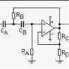
The very good Xmax figures led me into trying my favourite vented box Keele alignment where you have a high pass filter with 6db of boost at the same frequency as fb. For a 7 litre box this was 40.5Hz.
However you need to lower the Qts to 0.47 by using an amplifier with negative output resistance.
Here is the Unibox trace
Not bad for a 4 in driver
If anyone is interested in a kit to do the filter and negative resistance amp please e-mail me
However you need to lower the Qts to 0.47 by using an amplifier with negative output resistance.
Here is the Unibox trace
Not bad for a 4 in driver
If anyone is interested in a kit to do the filter and negative resistance amp please e-mail me
Attachments
Whoops! The unibox normalised my filter so that the peak was at 0dB
So it lowered the level by 6.5dB giving a false impression of the excursion. You can only get about 5 watts at 40Hz before running out of Xmax, with this alignment.
The usual way around this is not be so greedy with bass extension. But this would mean you have to go up to about 55Hz for fb
The 40Hz from a 4in driver in a 7 litre vented box is so impressive I am going to have a protection circuit which uses a Vactrol type device. This has a LDR which will change the resistor RB in the boost filter to cut the boost. I am going to make my own Vactrol type device from an LDR and a LED with some heat-shrink tube.
The LED will be fed by a Low pass filter and a zener so that only low frequency high level signals activate the the protection
Attachments
- Status
- This old topic is closed. If you want to reopen this topic, contact a moderator using the "Report Post" button.
- Home
- Loudspeakers
- Full Range
- FR125S post break-in T/S parameters