I figured it out!! (the cathode cap answer).
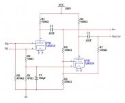
See the schematic below. Leave global NFB and C3 out of the picture.
When V1A is turning on, V1B is turning off. The current through R1 shouldn't change. This is exactly how it acts in the emulator. If it's not changing, C3 isn't required.
Now, lets add global NFB (but leave C3 out). V1A will receive negative feedback on it's cathode, but, R2 allows some of that signal to get to V1B's cathode in the form of positive feedback. Adding C3 prevents NFB from getting to V1B's cathode.
So the reason it didn't work in the emulator, but worked on the bench, is because I didn't account for global NFB.
I love knowing WHY and not just soldering stuff together.
Attachments
If I "eliminate" R4 (as in remove it) then there's no grid resistor on V1B.
It doesn't need a grid resistor; it will get its grid reference from the grid leaks of the *power valves*. That's why I showed them in post #15. (Unless the output stage is fixed biased)
You should really include the power valve grid leaks in your simulation anyway, as they will affect the balabnce of the PI.
Yes, the second triode should operate with unity gain, so it won't amplify vibrations very much. Although at these gain levels, I wouldn't expect you to have microphonic problems in any case...One thing I noticed right away was the floating paraphase has less microphonics then the standard paraphase. Could that be due to the second triode running "wide open" in a normal paraphase? The floating paraphase second stage's gain is much less due to the local feedback around the tube correct?
Last edited:
You should really include the power valve grid leaks in your simulation anyway, as they will affect the balabnce of the PI.
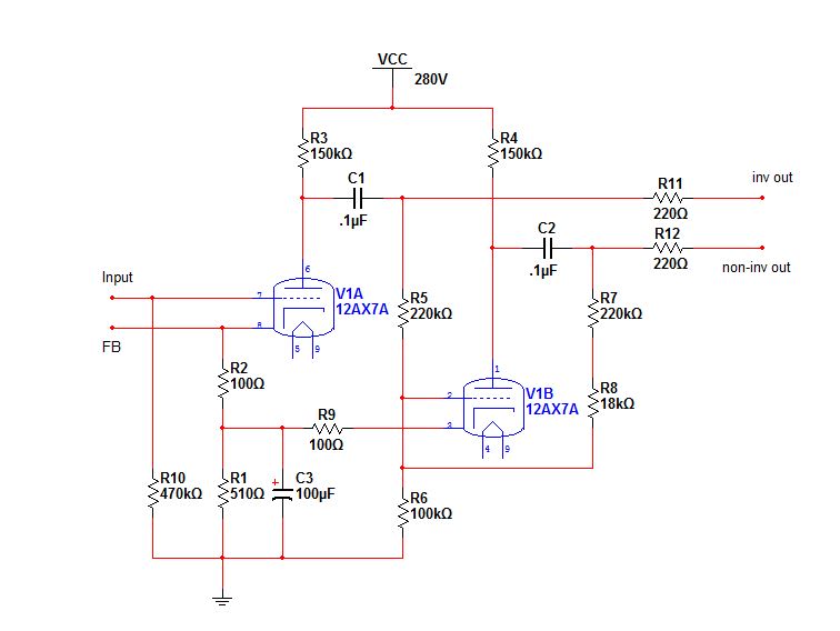
The resistors used in the PI (R5, R6, R7) are the output tube leak resistors.
Awkward? It's just very simple. If I ever go fixed bias on the output stage I'll need the extra resistors and caps but that's a big if unless I find an easy fixed bias method that auto adjusts.
How symmetrical is acceptable? It's currently less then 1v off at full output.
I've been flipping through some Santana, Christopher Cross, ELO, Supertramp, and some classical as well. Quite a variety of songs I know and they all sound good. I'm listening for missing pieces or discovery of new ones.
How symmetrical is acceptable? It's currently less then 1v off at full output.
I've been flipping through some Santana, Christopher Cross, ELO, Supertramp, and some classical as well. Quite a variety of songs I know and they all sound good. I'm listening for missing pieces or discovery of new ones.
Have a look at this schematic. It has a more symmetrical output by decreasing the feedback around V1B by adding R8.
Does adding R8 cause any significant issues? It makes the top output tube see a 1M grid leak and the bottom output tube see 1M+22k grid leak.
I'm also trying to get a little more gain out of the PI. The plate resistors were changed from 100k to 150k and cathode resistor adjusted slightly so the PI's plates are 1/2 B+.
The other question I have is if the 12AX7's grid is sitting at ~1v, anything over 2v peak-peak would drive it into clipping correct? So if I require my amp to accept a 4v p-p signal I'd simply use a 1/2 resistor divider on the input matched to w/e input impedance I needed?
Attachments
Last edited:
1M is quite a lot for an output tube... are you sure that doesn't exceed the maximum allowable value?It makes the top output tube see a 1M grid leak and the bottom output tube see 1M+22k grid leak.
The other question I have is if the 12AX7's grid is sitting at ~1v, anything over 2v peak-peak would drive it into clipping correct? So if I require my amp to accept a 4v p-p signal I'd simply use a 1/2 resistor divider on the input matched to w/e input impedance I needed?
2Vpp would drive the PI to full output, no? But your power valves don't need hundreds of volts of grid drive...
Divide the necessary grid drive by the PI gain to find the input sensitivity. Then you may be able to add enough global feedback to set the input sensitivity to the desired amount.
For a new fixed bias idea that floats for better sonics check out Dave's EFB. It also doesn't need it's own PS and so far 3 different versions to use depending on the circuit it's used on.
Teaser Pics -- Fisher SA-100 clone in progress - Page 3 - AudioKarma.org Home Audio Stereo Discussion Forums
Also more info on the Tronola Electronics site for more info.
Dave's Lab
Teaser Pics -- Fisher SA-100 clone in progress - Page 3 - AudioKarma.org Home Audio Stereo Discussion Forums
Also more info on the Tronola Electronics site for more info.
Dave's Lab
Last edited:
1M is quite a lot for an output tube... are you sure that doesn't exceed the maximum allowable value?
2Vpp would drive the PI to full output, no? But your power valves don't need hundreds of volts of grid drive...
Divide the necessary grid drive by the PI gain to find the input sensitivity. Then you may be able to add enough global feedback to set the input sensitivity to the desired amount.
Looks like the 6V6 calls for 100k with fixed bias and up to 500k with cathode bias. Sound about right?
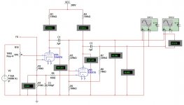
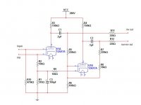
In that case, here's the updated schematic with a few mods.
R9 has been added so the bias on both triodes is identical.
R8 added to better balance the phases.
C1 and C2 increased due to reduction in R5 R6 R7 R8 to maintain low freq. response.
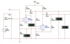
Take a gander at all the meter readings. Injected freq. is 10khz at 1v P-P (R1 at 50%).
Here's some various values at different frequencies.
Freq.___Offset___Output volts
20 hz___40mv___35.755
100 hz__39mv___37.210
1 khz___39mv___37.272
10 khz__39mv___37.367
20 khz__65mv___37.174
40 khz__128mv__37.180
R9 has been added so the bias on both triodes is identical.
R8 added to better balance the phases.
C1 and C2 increased due to reduction in R5 R6 R7 R8 to maintain low freq. response.
Take a gander at all the meter readings. Injected freq. is 10khz at 1v P-P (R1 at 50%).
Here's some various values at different frequencies.
Freq.___Offset___Output volts
20 hz___40mv___35.755
100 hz__39mv___37.210
1 khz___39mv___37.272
10 khz__39mv___37.367
20 khz__65mv___37.174
40 khz__128mv__37.180
Attachments
Last edited:
They don't especially need to be identical. 100R doesn't make a huge difference. Since you're clearly willing to add another resistor, I would still recommend getting rid of the 100k grid leak and your extra 100R bias resistor, and using separate grid leaks for the power valves instead. Same number of parts as you have now, but you don't need to worry about the power valve grid leak value when you adjust the PI, and the PI triode can be less heavily loaded and easier to obtain correct balance.R9 has been added so the bias on both triodes is identical.
You might also consider LED bias, to get rid of the bypass cap. One less part.
To save parts.What's the use of a common cathode resistor if it is decoupled ?
SO both triodes have identical bias voltage. Please read the thread.Why an extra 100 ohm on the cathode of the fase-inverter
I could play with it some more but it's so close to symmetrical using common resistor values. I could add a trimmer pot but 40mv difference between phases is pretty good.
I've listened to it for hours and everything sounds great.
I'll try it with separate grid leak resistors because I'm considering going to fixed bias on the output stage if I find a simple way to do it.
I've listened to it for hours and everything sounds great.
I'll try it with separate grid leak resistors because I'm considering going to fixed bias on the output stage if I find a simple way to do it.
:lol:To save parts.
SO both triodes have identical bias voltage. Please read the thread.
Mona
So my friend brought over his Magnavox 8802 (tiny OPTs) which sounds a lot like my 9302 but not as much low end. We spent about 5 hours listening to them (on 4 different sets of speakers) and my DIY 6V6/12AX7/PP amp won our listening test by far. The imaging is great. There were times that instruments sounded like they were coming from various disconnected speakers. The bass is deep, tight, and full. The midrange tamed and clear, and highs that breathe. I'm not adding much feedback either. I don't know how to calculate the feedback but the resistor is 15k off the only output tap at 8-ohm.
I remember something I wanted to ask you guys. Should there be a cap on the NFB signal to prevent DC voltage (at the preamp cathode) from getting to the output?
I remember something I wanted to ask you guys. Should there be a cap on the NFB signal to prevent DC voltage (at the preamp cathode) from getting to the output?
Last edited:
We liked this design so much we implemented it into my friends Maggie 8802 chassis. Having modded this poor thing so many times it's hard to do an A/B with the original design but first he rewired one channel from a 6EU7 to a 12AX7 with a proper standard paraphase inverter. We liked the 12AX7 better. Then the other 6EU7 also went to a 12AX7 but with the floating paraphase circuit. Tonight it gets Edcor OPTs.
This is where it's at currently. R7 and R8 could probably be a 240k but it's very well balanced.
This is where it's at currently. R7 and R8 could probably be a 240k but it's very well balanced.
Attachments
Two Questions: Would this be usable with 6L6 family outputs?
Also, which model of Edcor OTs are you using?
My understanding of technical / theory issues is limited but I've been a fan of several amps that use paraphase including Magnavox, Voice of Music and the Pilot 232 mentioned earlier. I also built a PP 6B4G that uses a paraphase front end using 2C22s and breadboarded a 6CB5 using paraphase (regular and floating) 6GK5s.
. . . Charlie
It shouldn't have any trouble with 6L6s. I have a 6L6 build in the works and plan on using this circuit with it. There may be better, more complicated, designs out there but for raw simplicity and capability I'm very happy with it.
My friend is using a GXPP series in his 6V6 amp. https://www.edcorusa.com/gxpp15-4-8k It's going in the car eventually hence the 4 ohm tap.
My friend is using a GXPP series in his 6V6 amp. https://www.edcorusa.com/gxpp15-4-8k It's going in the car eventually hence the 4 ohm tap.
- Status
- This old topic is closed. If you want to reopen this topic, contact a moderator using the "Report Post" button.
- Home
- Amplifiers
- Tubes / Valves
- Floating Paraphase.