That heat sink I got stinks.. wish it was twice as beefy. I should probably buy another. It only cost me $9.
My brother is a machinist and probably has a scrap piece of aluminum laying around that he can cut into 150x60mm .. say 3/8" thick. Then that could be bolted to this other cheaper heat sink with conductive paste in the middle, to make a beefier heatsink. Would this work well?
I have 8 of these identical heat sinks and they work fine for most projects under 100w. They are $10 for 2 from Ali so great value.
If you find that things get a little hot, the addition of a very light $1 50mm 12v computer CPU fan with qnty 4 x 220R resistors in parallel between 12v and fan, allows the heatsink temp to drop to maybe 5 or 10 deg above ambient and is silent as it spins much slower. Use a 7812 to drop your 32v down to 12v for the fan.
Here is my fan and heatsink cooling two FX8 MOSFET amps. Barely warm to the touch.
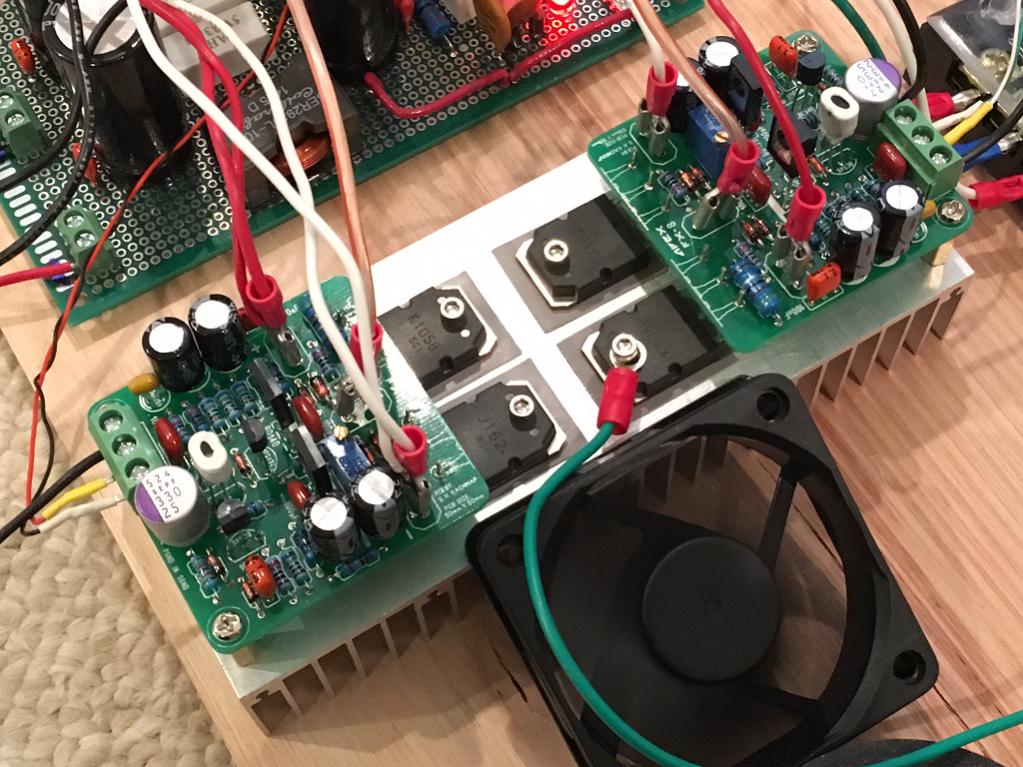
The resistor slow down trick really works - dead silent.
I have 8 of these identical heat sinks and they work fine for most projects under 100w. They are $10 for 2 from Ali so great value.
If you find that things get a little hot, the addition of a very light $1 50mm 12v computer CPU fan with qnty 4 x 220R resistors in parallel between 12v and fan, allows the heatsink temp to drop to maybe 5 or 10 deg above ambient and is silent as it spins much slower. Use a 7812 to drop your 32v down to 12v for the fan.
Here is my fan and heatsink cooling two FX8 MOSFET amps. Barely warm to the touch.
The resistor slow down trick really works - dead silent.
How much noise will the fan and voltage regulator inside the case add to the signal or output ? A drop from 32v to 12v is quite a drop right? Will the voltage regulator get really hot or is there not enough current to worry about that?
Really thinking about adding 3/8 thick aluminum bar to the back of the heatsink, behind the fins. Not enough room to put it on the chip side. You think if I added thermal compound to the edges of the fins that it will transfer heat well to the aluminum bar?
Last edited:
With a 10uF ceramic plus 0.1uF film decoupling cap on 7812 input I don't have any electrical noise. The current is low so not much heat but if you wanted to, add maybe qnty 10 x 1N400x diodes in series before the input to the 7812 and drop some voltage without too much heat. You could put regulator on main sink and that works too.
Here is my class A ACA amp that is not even warm with small fan and 7812 on heatsink.
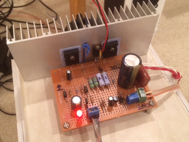
Here is my class A ACA amp that is not even warm with small fan and 7812 on heatsink.
I would just buy another identical HS and be done with it. With lots of passive HS as long as you have air vents nearby I wouldn't worry getting about direct (line of sight) airflow. Mount them with a couple of short standoffs and long self tapping metal screws. My analysis shows the need 2x the heatsinking over the plain metal tabbed chip-amp package.
A fan and regulator could made to work off of the main DC rail but youre just adding ~ 7W inside the box and potentially some other unreliable and noise factors. Alternatively you could try to add ~20 turns of hookup wire around the toroid to power the DC fan through a half wave rectifier and a spare smoothing cap.
A fan and regulator could made to work off of the main DC rail but youre just adding ~ 7W inside the box and potentially some other unreliable and noise factors. Alternatively you could try to add ~20 turns of hookup wire around the toroid to power the DC fan through a half wave rectifier and a spare smoothing cap.
Last edited:
The adding hookup wire to a toroid is a cool idea. Never thought of that to tap more power off of one. That would reduce the heat from the 7812 and decouple from the main power supply any noise issue.
the fan noise I speak of is audible, the electrical DC fan noise is very easy to decouple in conjunction PSRR rejection to no worries, besides 'reliable' fans aren't the most quiet ones. Thermal cutout & fan switches would be helpful, but passive HS is best of all, disregarding size, weight , and costs.
Last edited:
Fan noise is proportional to blade RPM (I think cubic relation) so reduce speed to bare minimum and noise goes down drastically. Have you tried adding resistors to your fans? I find it takes about 50ohms with 12v fan before the brushless DC motor goes slow enough. It's very very quiet. Heatsink runs warmer than full speed fan to be sure but a lot cooler than no fan.
The RCA to PCB twisted leads look good.
The stacked PCBs look good.
Try powering on via your Mains Bulb Tester and see how quickly the chipamp warms up.
Try the CHG direct to chassis. See if you get some hum due to the loop in the interconnect cabling.
You will probably have to insert a Disconnecting Network between CHG and Chassis. That will not cure the hum, but it should reduce it slightly.
You may be able to add HBRR and HBRL to the PCBs to attenuate the hum some more and make it low enough to be inaudible (depends on the sensitivty of your speakers) and maybe unmeasureable (<0.1mVac)
The RCA to PCB twisted leads look good.
The stacked PCBs look good.
Try powering on via your Mains Bulb Tester and see how quickly the chipamp warms up.
Try the CHG direct to chassis. See if you get some hum due to the loop in the interconnect cabling.
You will probably have to insert a Disconnecting Network between CHG and Chassis. That will not cure the hum, but it should reduce it slightly.
You may be able to add HBRR and HBRL to the PCBs to attenuate the hum some more and make it low enough to be inaudible (depends on the sensitivty of your speakers) and maybe unmeasureable (<0.1mVac)
"loop in the interconnect cabling": can you explain what the loop is and what interconnect you are talking about? sorry I am really new to all this but learning
") thanks!
thanks!read D.Joffe, he expalins why the loops cause interference and shows how to attenuate the interference.
It is quite technical, so be prepared to read it three times and get your questions ready.
Fig1 is a common fault in many PCB layouts. Hopefully your PCB avoids that.
Fig4 shows the interconnect problem feeding a stereo amplifier.
Fig5 is the solution.
It is quite technical, so be prepared to read it three times and get your questions ready.
Fig1 is a common fault in many PCB layouts. Hopefully your PCB avoids that.
Fig4 shows the interconnect problem feeding a stereo amplifier.
Fig5 is the solution.
Attachments
Last edited:
I would just buy another identical HS and be done with it.
So you are saying slap another heatsink to the back of the other where the solid side of the second heat sink butts up against the fin edges of the other -- i.e. instead of the aluminum bar I was suggesting?
read D.Joffe, he expalins why the loops cause interference and shows how to attenuate the interference.
It is quite technical, so be prepared to read it three times and get your questions ready.
Fig1 is a common fault in many PCB layouts. Hopefully your PCB avoids that.
Fig4 shows the interconnect problem feeding a stereo amplifier.
Fig5 is the solution.
It's nothing to do with the fact the PCB's are stacked and connected with that solid core copper wire right? And that only 4 wires are coming from the DC supply board instead of 8?
At least I don't have the CHG of the PCB's connected to protective earth chassis screw anymore
No it's a common fault in dual channel amplifier when connected to a source that uses a common ground for the two outputs.It's nothing to do with the fact the PCB's are stacked and connected with that solid core copper wire right? And that only 4 wires are coming from the DC supply board instead of 8?
At least I don't have the CHG of the PCB's connected to protective earth chassis screw anymore
Monoblocks don't have this, all stereo amplifiers potentially have this and D.Joffe shows why.
No it's a common fault in dual channel amplifier when connected to a source that uses a common ground for the two outputs.
Monoblocks don't have this, all stereo amplifiers potentially have this and D.Joffe shows why.
Thank you. I'll try digesting it at a later time. For now I guess I'll just trust Brian's PCB. I can always try and upgrade the amp later. Or maybe I'll run into another one of these commercial tape player enclosures and use the other spare aluminum bar faceplate I have for it
Making a dual monoblock setup Here is the schematic for the LM3886 chipamp.com AMP board:
And here is the schematic for the power supply board:
An externally hosted image should be here but it was not working when we last tested it.
And here is the schematic for the power supply board:
An externally hosted image should be here but it was not working when we last tested it.
Oh dear.
It needs a lot of small changes to get the best from it.
This has been discussed many times in previous chipamp Threads.
The 3A fuse for 110/120Vac operation is too big.
It could pass 6A continuously during a fault condition and rupture after 30minutes. By then your furniture could be on fire from the heat of that 700W glow in the dark box.
The 2A fuse for 220/240Vac is even worse advice.
Oh dear.
It needs a lot of small changes to get the best from it.
This has been discussed many times in previous chipamp Threads.
The 3A fuse for 110/120Vac operation is too big.
It could pass 6A continuously during a fault condition and rupture after 30minutes. By then your furniture could be on fire from the heat of that 700W glow in the dark box.
The 2A fuse for 220/240Vac is even worse advice.
The 3A fuse is because of the transformer size. He recommended 250VA to 300VA. I have 300VA. Do I need to add a fuse between the secondaries and dc supply board for safety?
- Status
- This old topic is closed. If you want to reopen this topic, contact a moderator using the "Report Post" button.
- Home
- Amplifiers
- Chip Amps
- Flea Market Bargain -- Enclosure for my LM3886