I believe that dac is single supply (+ and ground) what you have posted is a bipolar supply. Not gonna work. Also, it's not really suited for the task imo.
I would look at a lm317 supply or if you want to get fancy the salas shunt or Jung super reg. But really, if there is a lm transistor regulator in the dac the performance is kind of dictated by that last regulator anyways. You can clean up the supply before that regulator but the output impedence, etc. is always going to be set by that internal reg.
Personally, I'd try batteries.
Just use half of it for single rail.
Btw, I used this to clean up the output of a 53v Abletec SMPS and the ripple is now about 1mV or less. The SMPS did not go crazy trying to drive the caps in here. I wonder if it can work for a standard 24v wall wart brick.
I would not have believed it myself but here is the measurement with a VHEX+ amp drawing probably circa 750mA quiescent.
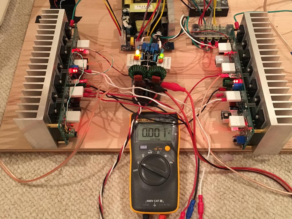
That $25 Abletec is overkill for a lot of amps as it is 53v rails but may be an indicator that we can try CRCLC filters on SMPS that don't go nuts with a cap load.
Last edited:
I think it would help to show what Nelson Pass uses on his First Watt amps.
Scroll down and you will find the PSU schematic.
http://www.firstwatt.com/pdf/prod_f1_srv.pdf
The amp circuit schematic shows a desired input voltage of 24v
Scroll down and you will find the PSU schematic.
http://www.firstwatt.com/pdf/prod_f1_srv.pdf
The amp circuit schematic shows a desired input voltage of 24v
Last edited:
I think it would help to show what Nelson Pass uses on his First Watt amps.
Scroll down and you will find the PSU schematic.
http://www.firstwatt.com/pdf/prod_f1_srv.pdf
The amp circuit schematic shows a desired input voltage of 24v
Thanks. Been looking through the F1 service manual link you gave me, and reading about the power supply and AC grounding & the termsistors, trying to understand as much as I can with my limited knowledge -- understand about 70% of it or so.
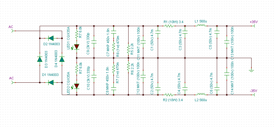
I understand capacitors and how they smooth things after rectification. (Ceramic disc filtering caps I have an even more limited knowledge of.) But could you explain to me what R5-R8 are used for between C4 and C7? And why current would ever go through there instead of the path of least resistance?
He called this a CRC type storage bank. I am only familiar with capacitor only storage bank with no resistors. I built a linear regulated power supply (on perf board) for my commodore 64 using 9v toroidal, rectifying diodes and the 2A version of the 7805. Used caps on the input and output but no resistors on either side.
My knowledge of AC to DC supply so far: I know what the rectifying diodes do, turning a 60hz sine wave into a 120hz wave that's all on the positive side. [I've actually traced the current flow from alternating to a DC load through the 4 way rectifier and understand how it works.] I know the 120hz half wave constantly charges up the "smoothing cap" (electrolytic) and the smoothing cap provides a somewhat steady DC voltage, given reasonable load and that there is more ripple the higher the load. I also know that many electrolytics in parallel just function as Ctotal = C1 + C2 + C3 .. + Cn. Those resistors R5-R8 between C4 and C7 just don't make any sense to me -- my knowledge is too limited.
An externally hosted image should be here but it was not working when we last tested it.
Last edited:
The current though the diodes is not constant. Current only flows when the half-wave voltage is higher than the voltage of the capacitors. This results in 120 short current pulses per second to the capacitors. The R slows the pulsing current into the second C and thereby smoothing the voltage.
Thanks. Been looking through the F1 service manual link you gave me, and reading about the power supply and AC grounding & the termsistors, trying to understand as much as I can with my limited knowledge -- understand about 70% of it or so.
I understand capacitors and how they smooth things after rectification. (Ceramic disc filtering caps I have an even more limited knowledge of.) But could you explain to me what R5-R8 are used for between C4 and C7? And why current would ever go through there instead of the path of least resistance?
He called this a CRC type storage bank. I am only familiar with capacitor only storage bank with no resistors. I built a linear regulated power supply (on perf board) for my commodore 64 using 9v toroidal, rectifying diodes and the 2A version of the 7805. Used caps on the input and output but no resistors on either side.
My knowledge of AC to DC supply so far: I know what the rectifying diodes do, turning a 60hz sine wave into a 120hz wave that's all on the positive side. [I've actually traced the current flow from alternating to a DC load through the 4 way rectifier and understand how it works.] I know the 120hz half wave constantly charges up the "smoothing cap" (electrolytic) and the smoothing cap provides a somewhat steady DC voltage, given reasonable load and that there is more ripple the higher the load. I also know that many electrolytics in parallel just function as Ctotal = C1 + C2 + C3 .. + Cn. Those resistors R5-R8 between C4 and C7 just don't make any sense to me -- my knowledge is too limited.
An externally hosted image should be here but it was not working when we last tested it.
Quote:
Component values are designed so that the resistance of R1 is much greater than the reactance (XC) of C2 at the ripple frequency. C2 offers a very low impedance to the ac ripple frequency. Thus, the ac ripple senses a voltage divider consisting of R1 and C2 between the output of the rectifier and ground. Therefore, most of the ripple voltage is dropped across R1. Only a trace of the ripple voltage can be seen across C2 and the load.
From:
Resistor-Capacitor (RC) Filters
It was the best description I could find.
") Look forward to reading more about RC CRC filters. Thanks for the info and links.
Look forward to reading more about RC CRC filters. Thanks for the info and links.
- Status
- This old topic is closed. If you want to reopen this topic, contact a moderator using the "Report Post" button.
- Home
- Amplifiers
- Chip Amps
- Flea Market Bargain -- Enclosure for my LM3886