Hmm, depending on the room, that may be the wrong advice. In fact, in most situations, I would say Silent may be better off using the MTM.Nice, but you are going to have lobing issues with such a large mtm. Id suggest ditching one of the mids.
When using a single mid, the main lobing pattern will be vertically assymetrical with most types of crossover and create more floor-bounce issues. On top of this the angles of the lobes are such that what hits the floor is radically different than what hits the ceiling, and the difference in spectral balance can be bothersome to the hearing system. Translation: you may hear much more of the room. The MTM version is likely to create LESS of a lobing issue not more, because it keeps vertical symmetry and the floor/ceiling bounce are more spectrally coherent with each other.
If it's comb filtering you're worried about, the MTM may also be better than the single mid - even though there is potential for more comb filtering, the peaks and nulls as long as the arrival times are close to exactly the same. Meaning: the mids must be very closely aligned so they are at the same distance to the ears.
That being said, there are exceptions to the rule! I've built both types, and in some rooms, I have seen specific instances where a single mid subjectively performs better.
But as a general principle, the MTM (also called D' Appolito array) will interface better with most rooms due to the symmetrical lobing patterns. It's no accident that most of the best HT designs use MTM rather than single mids.
Did a bit of tweaking...
A further refinement would be to shape the profile of the supporting structure behind the tweeters to look like propeller edges. This would minimize the reflection issue to the point where the distance from the tweeter is almost not an issue. BTW, the previous MTM version that you have drawn, even with the flat and reflective edges, is not going to present much of a problem anyway. But if you want to push the envelope, taper that piece front and back so that the sound flows around it. It's fairly easy to do this, and it has the potential to look much nicer, so I would vote in favor of this option for sure!
A good experiment to visualize the effect of this is to put a knife under running water. If you turn it so the flat is perpendicular to the flow you get lots of splashing. Turn it so the edge "cuts" into the water and the flow is so unobstructed it makes almost no difference at all if the knife is there or not. And it doesn't much matter if the knife is fat or skinny, does it?
So you could make your supporting beams fairly thick, and so long as they taper down to a thin profile at the edge, the flow will be very good and reflections will be minimal. With a knife edge the distance issue is very much minimized and you can design for the best looks.
Suggestion: By knife edge, I mean something closer to what you see on a propeller blade. It doesn't have to be dangerously sharp, and accidents can and do happen, so round off the edges to look like a propeller blade.
There was a paper posted here recently about the mtm subject. (posted by member "line source") While that configuration can sum flat on axis .. the off axis response can be the headache. There were some good guidelines to follow within the paper. Perhaps it's worth a read?
Here it is: http://www.birotechnology.com/articles/VSTWLA.html
Some other worthwhile reading here too: http://www.excelsior-audio.com/Publications.html
Here it is: http://www.birotechnology.com/articles/VSTWLA.html
Some other worthwhile reading here too: http://www.excelsior-audio.com/Publications.html
Last edited:
Silent S
I am worried that you are going through the exact route that Stig has taken:
no baffle, two many drivers, too many crossover points.
Stig has since moved to a two way system with planar B&G radia drivers
MTM is difficult, WMTMW is a no-go. That is not my opinion; Lynn Olson says so.
I am worried that you are going through the exact route that Stig has taken:
no baffle, two many drivers, too many crossover points.
Stig has since moved to a two way system with planar B&G radia drivers
MTM is difficult, WMTMW is a no-go. That is not my opinion; Lynn Olson says so.
Thank you all for the varied responses. Jack we did a similar thing many years ago with the crankshafts in our cars, called knife edging, to a help the crank cut the through the oil in the sump, so I am familiar with the concept.
I was planning to radius the leading edge with a round over anyway, but I might use a straight chamfer instead to give a sharper leading edge.
Whether I do Mw-Mw-M-T-M-Mw-Mw or M-M-T-Mw-Mw-Mw-Mw really doesn’t cause any real issues from a design stand point as long as I settle on one or the other before I start cutting wood.
Better yet make some crude prototypes of each and compare, then later refine the edges, etc. My opinions and those of others can be helpful, but it's best to experiment and find what you like best.Whether I do Mw-Mw-M-T-M-Mw-Mw or M-M-T-Mw-Mw-Mw-Mw really doesn’t cause any real issues from a design stand point as long as I settle on one or the other before I start cutting wood.
I think the WMTMW approach may well be the best, especially if you can use steep slope "constant group delay" filters like DEQX offers.
I just showed this to my partner and she said the same thing as I was thinking, we have come full circle back to the ugly man again. Is there no escaping the ugly man? http://www.diyaudio.com/forums/multi-way/211345-interesting-designs-5.html
Attachments
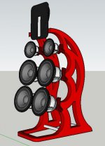
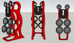
These renderings look interesting, but there are some practical issues:
1) There's no benefit to leaving the woofers unbaffled. It just wastes efficiency. This is StigErik's conclusion and generally confirmed by others who've made swinging dipoles.
2) It doesn't make sense to place the mids side by side. Your tweeter has a tall diaphragm so it has limited vertical dispersion. The mids may as well match that by stacking vertically, as you had before. Or if you can get enough output from one driver just place it below the tweeter. I would suggest TMM is better than MTM given the large size of the tweeter.
3) The structure looks pretty hard to build with the two upright elements flowing together across the bottom. Try making some mini versions with cardboard to see how strong it is and how well it holds together. It's possible you could do this with one big piece of metal plate that's folded across the bottom. See below, someone posted this awhile back (don't recall where).
Thanks TJ for your input.
1. Does this apply to mid woofers as well? As the 18" woofers will be in a H frame. Guessing it may since the mid woofers go down to about ~100hz where there is some serious roll of.
3. Structure would be easier as would use the same router jigs twice per speaker. The piece across the front would be a separate piece that would be routed once glued in place (or not used at all).
Back to the drawing board to come up with a baffled version that doesn't look boring.
I bought a new external sound card? (Roland AU 55) the other day and a new Dayton EMM-6 mic to get better measurements out of the Ground Sound / XOver Wizard 2 Advanced software.
Rather than pot guesses at what I need it is time to do a bit measuring to determine what my real needs are. I half feel like I am throwing drivers at this project for the sake of it...
So what I might do is try a few measurements of 2 and 4 mid woofers and try measuring with and without a baffle. I have been far from scientific with this build so far, time to let some measurements dictate it course.
Having said that up to now I have only had my ears to work with because I couldn't get the software to work until I bought the right equipment and Robert from Ground Sound gave me a hand.
Spent a little time yesterday trying to take some measurements of the current prototype 4 way.
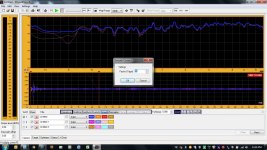
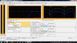
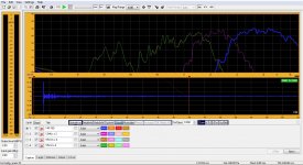
After a bit of playing around with the crossover slopes I have come up with the following graph.
No filters applied, no delay etc.
Woofer is crossed over a little higher than I like but that is compensate for a lack of a proper baffle set up on the woofer.
Note: measured at 85cms from speaker, 85cms from floor between tweeter and mid.
Attachments
Last edited:
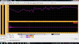
Leaving the same crossover slope in place (no optimisation) and moving the crossover from 250hz down to 85hz reveals the roll off of the 18WUs.
I could EQ them back up a bit, but might see what happens when I mount them on a baffle. I expect to find I may not need such a big correction.
I could EQ them back up a bit, but might see what happens when I mount them on a baffle. I expect to find I may not need such a big correction.
Attachments
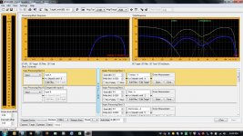
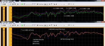
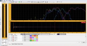
At first I tried adding +3 to the mid and -3 to the mid woofer (bottom part of picture)
Which made me wonder what would happen if I was to double up the mid (12MU) as per the original intent. (top part of picture)
Interesting findings...
I found that doubling up the driver (in series) made very little difference where adding 3dB to both the the single and double 12MU had a greater impact.
I put this down to the limited bandwidth of the XOver. When placing my ear up against one of the 12MU vs one of the 18WU the is a very audible difference in SPL.
So it would seem there is little to gain by adding the second 12MU.
Attachments
Still making progress with learning how to use the software and how to get some meaning results out of the readings I am capturing.
I would have never managed to get this off the ground without Roberts extremely patient assistance. So far I am very happy with the Ground Sound DCN28, but the help section of the included software (another vendor) is terrible. The customer service at Ground Sound is second to none.
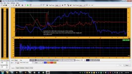
While progress is slow I sort of learned a new trick yesterday. Using the Group Delay I can apparently determine where reflections are showing up in my measurements. I still haven’t worked out how to filter them out (if I can at all) but access to this sort of data can only make proper placement in the room so much better, and perhaps even help with some external acoustic dampening down the track.
Not overly worried about how to use this feature properly yet as I am still trying to work through proper cable connections and electrically configuring the hardware I need to use with the software.
Karsten hang in there help is coming… I hope to get to a point in the not too distant future where I understand the more advanced software features much better. I had my first go at using the auto EQ feature the other day, still a bit hit and miss but overall the learning level is coming up.
I would have never managed to get this off the ground without Roberts extremely patient assistance. So far I am very happy with the Ground Sound DCN28, but the help section of the included software (another vendor) is terrible. The customer service at Ground Sound is second to none.
While progress is slow I sort of learned a new trick yesterday. Using the Group Delay I can apparently determine where reflections are showing up in my measurements. I still haven’t worked out how to filter them out (if I can at all) but access to this sort of data can only make proper placement in the room so much better, and perhaps even help with some external acoustic dampening down the track.
Not overly worried about how to use this feature properly yet as I am still trying to work through proper cable connections and electrically configuring the hardware I need to use with the software.
Karsten hang in there help is coming… I hope to get to a point in the not too distant future where I understand the more advanced software features much better. I had my first go at using the auto EQ feature the other day, still a bit hit and miss but overall the learning level is coming up.
Attachments
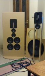
A new baffle is born…
Now that I am getting the hang of using the mic and collecting measurements, I have made up a new prototype baffle to do some direct comparison. I only finished late last night so I didn’t have chance to do much evaluating, but here are my very early findings.
The top end seemed to lack a very tiny amount of detail (not sure if this is related to a wide baffle close to the wall), and there is more bass although I don’t think it is as clean sounding.
I did throw the mic on to do some very quick snap shot figures. First measurements were done with the mic in line with each of the drivers (also 2 and 4 x 18WU measurements), the second lot were stationary in front of tweeter area (4 x 18WUs only).
Not the greatest comparison but rough enough to get some early findings. It still has a nasty dip around the 300Hz mark, but on the baffle the mid bass makes a comeback, which indicates there is still some more research to be done with the mid bass area. Possibly even look at making a U or H baffle for just the mid woofers. Both the tweeter and the mids seem a bit smoother in response, but I am keen to see if I can cut the baffle back a bit in the area of the tweeter and mids and still keep the smoother response.
Hope to do some more conclusive testing tonight.
Attachments
Yeah, try tapering the sides into the mids and tweeter. Like a pyramid. I like the midbass in a square quite a lot. Looks imposing and keeps overall height manageable.
Where is your crossover point btw the woofer and mids? Are they the same for the mid to woofer transition or do you accidentally have a gap programmed in there? Have you tried flipping the relative phase of the mids or woofers and have a look at the measurements? Where are those measurements taken from? You might be back too far and getting room effects added in more strongly than you want right now. I like to see a combination of closer measurements on the tweeter axis of no more than a foot away and then again at a meter and maybe 2 meters or the listening position. I use the closer ones to see what the drivers are doing with less room effects.
EDIT: I think I see now that the yellow is the midbass, purple is the mids and blue is the Raal, correct? Why run the midbass so high? You need to be looking at using those 12mu for more than just 2 octaves. That's a waste. Think more around 300-500Hz at least. Also, the entire bass range needs to come up. You need a dipole correction EQ as the low end is drooping too much.
Last edited:
- Status
- This old topic is closed. If you want to reopen this topic, contact a moderator using the "Report Post" button.
- Home
- Loudspeakers
- Multi-Way
- First time OB builder