If you are willing to try a new woofer, I will recommend the SB Satori woofers 5-6.5" they are the over all best mid-woofers I have tried. If you could go one size up, the old Scan Speak 18W/8535 is still my favorit Scan Speak midwoofer, especially for its midrange qualities.
I did use it. I just don't think the Satori is in the same league as the Seas Excel (may be the regular Seas) or ScanSpeak and for all the complaints I have with the Illum I still prefer it over the Satori.
Just finished the Nextel with the AirCirc and couldn't believe the difference. It's about $57 more expensive than the Satori dimple dome but I can guarantee it's a lot more better than $57. It's hard to put a price on it. With the Aircirc I think it's better than the Illum 5in everything considered. The Illum will always have better bass but the Nextel has almost everything else. If the Illum is the Porsche 918, the Nextel + Aircirc is the LaFerrari in that context. The Illum may be slightly smoother up top, but looking at a different way, the Nextel may have better detail up top.
Looking at Seas line up vs. ScanSpeak it seems to me they go about it in very different way. Seas seems to experiment with different types of material, whereas ScanSpeak mostly just use different variant type of paper, but rather concentrate on better motor design. Seas motor design relatively is more conventional. ScanSpeak may ultimately have better objective data, but I think Seas may offer a more interesting sound. I mean my ears may not be able to tell the difference between .03 vs. .07 third order distortion, but I can definitely tell the difference between good old poly cone vs. Nextel or Magnesium. Maybe ScanSpeak will some day offer a ceramic cone.
Looking at Seas line up vs. ScanSpeak it seems to me they go about it in very different way. Seas seems to experiment with different types of material, whereas ScanSpeak mostly just use different variant type of paper, but rather concentrate on better motor design. Seas motor design relatively is more conventional. ScanSpeak may ultimately have better objective data, but I think Seas may offer a more interesting sound. I mean my ears may not be able to tell the difference between .03 vs. .07 third order distortion, but I can definitely tell the difference between good old poly cone vs. Nextel or Magnesium. Maybe ScanSpeak will some day offer a ceramic cone.
Attachments
"After the LaFerrari fantasy
Waken to a nightmare
The disguised devil unaware
The devil itself unawared
Heaven pugatory hell
Thrice the path
Thrice the same
Circle we go
Religion faked science
All the same
The bitter remains
In my DNA"
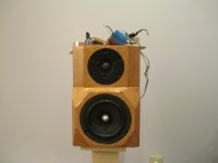
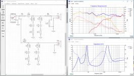
I guess that is what happens when you go from Seas and ScanSpeak down to SBAcoustic. Kind of like going to hell. Poly cones shouldn't have break up but somehow they manage to put break up in the poly cones. The best I could do is 12db roll off (or close to it). Anyway, my listening impressions coming up.
Waken to a nightmare
The disguised devil unaware
The devil itself unawared
Heaven pugatory hell
Thrice the path
Thrice the same
Circle we go
Religion faked science
All the same
The bitter remains
In my DNA"
I guess that is what happens when you go from Seas and ScanSpeak down to SBAcoustic. Kind of like going to hell. Poly cones shouldn't have break up but somehow they manage to put break up in the poly cones. The best I could do is 12db roll off (or close to it). Anyway, my listening impressions coming up.
Attachments
With a true 1st order Butterworth, assuming the drivers contribute zero acoustic roll-off and no phase shifts on their own, wouldn't the tweeter and the midrange be 90 degrees out of phase at the crossover point? If so what is the point of time alignment? (Except to offset the drivers to exactly cancel out the said 90 degree phase shift, but then it would have been phase alignment not time alignment.)
I have always thought that, conceptually, only even-order (2nd, 4th) crossovers (total electrical+acoustic) can be time-aligned. Correct me if my concept is wrong.
I have always thought that, conceptually, only even-order (2nd, 4th) crossovers (total electrical+acoustic) can be time-aligned. Correct me if my concept is wrong.
A perfect acoustic odd order Butterworth has 90° phase offset an any frequency, not just at the XO point (where of course it is most important). And to get there you must have no additional phase shift coming from time-of-flight offsets.
Butterworth is intended to be used with a proper M-T-M D'Appolito config or a coaxial, with M-T you'd need their vertical spacing to be closer than what can be practically realized.
Even order XO (Linkwitz-Riley) has constant zero inter-driver phase offset and again you must avoid additional time-of-flight or the main beam won't be on-axis.
Often, some time-of-flight induced phase skewing can be mitigated by adjusting frequencies and sharpness of the transition "knee" with little effect on the summed flatness and lobing.
OTOH, phase contribution from the drivers themselves can be dealt with the same procedure plus intentional time-of-flight differences to get a practical XO, it's all about the right compromises you gotta choose.
Side note:
You can also construct a 3rd order XO that has, for example, constant 60° phase offset (actually, you can define an arbitrary phase offset) which has less lobing issues than Bu3 yet steeper final slopes than a LR2 but almost the same total phase rotation of the sum (as does a Bu3). The transition region is a bit softer that Bu3 but sharper that LR2, drivers are about 4.5dB down at the XO point.
I call this a LRB2.5 (Linkwitz-Riley/Butterworth Hybrid 2.5th order) and use it quote often for W-M (or W-M-W) XO because it is as "fast" as LR2 yet offers steeper slopes and acceptabe lobing.
Last edited:
A perfect acoustic odd order Butterworth has 90° phase offset an any frequency, not just at the XO point (where of course it is most important). And to get there you must have no additional phase shift coming from time-of-flight offsets.
Butterworth is intended to be used with a proper M-T-M D'Appolito config or a coaxial, with M-T you'd need their vertical spacing to be closer than what can be practically realized.
Even order XO (Linkwitz-Riley) has constant zero inter-driver phase offset and again you must avoid additional time-of-flight or the main beam won't be on-axis.
Often, some time-of-flight induced phase skewing can be mitigated by adjusting frequencies and sharpness of the transition "knee" with little effect on the summed flatness and lobing.
OTOH, phase contribution from the drivers themselves can be dealt with the same procedure plus intentional time-of-flight differences to get a practical XO, it's all about the right compromises you gotta choose.
Side note:
You can also construct a 3rd order XO that has, for example, constant 60° phase offset (actually, you can define an arbitrary phase offset) which has less lobing issues than Bu3 yet steeper final slopes than a LR2 but almost the same total phase rotation of the sum (as does a Bu3). The transition region is a bit softer that Bu3 but sharper that LR2, drivers are about 4.5dB down at the XO point.
I call this a LRB2.5 (Linkwitz-Riley/Butterworth Hybrid 2.5th order) and use it quote often for W-M (or W-M-W) XO because it is as "fast" as LR2 yet offers steeper slopes and acceptabe lobing.
Although you have stated some well defined guidelines, in my personal experience, it's never black and white ... that is the xover never going to be neatly categorized into perfectly any predefined topology. That is whatever works. It's like Bruce Lee was trying to fight the bad guy. Whatever kicks or punches he uses it's hard to say whether it's taekwondo or Tae something else.
You certainly meant power response.It is the 90 degree phase difference that allows both the power through the crossover and the axial response to be flat.
Well, part of the power response is the lobing pattern and basically you don't want to have any lobing (of-axis nulls and peaks) at all. Mostly it is unavoidable, then at least you don't want to have downward pointing peak at the XO as this will be reflected on the floor and makes very unatural height presentation. Upward pointing beam is less bad, but still not good. That's why I stick to zero inter-driver phase offset for a typical M-T XO with the ususal suspects (6.5" + 1"), whereas larger phase offsets for M-T-M arrangement, where the details of the lobing pattern can be adjusted by inter-driver phase. With this you can get decent lobing and power response even when the vertical spacing is larger than for textbook D'Appolito which is based on (the arbitrary choice of) 90° inter-driver phase.
Power response irregularities at the XO from choice of XO are overrated IHMO. One should start to worry about that once one has fixed the overall power reponse by using a proper waveguide on the tweeter to give it the same radiation pattern as the woofer throughout the whole XO region.
Quite so. As I said, it's all about compromise. The choice of drivers and their implementation on the baffle etc gives us a tolerance band of the actual response shape for that driver within the driver will work reasonably. Within that zone you can basically do whatever works. Still I'm very strongly convinced that systematic crossover design gives the best result overall. That is, make your mind about which theoretical acoustical target functions (there is an infinite amount of those, not just the commonly known textbook ones) will do best for the intended purpose (your set of compromises) and then EQ the drivers to get there. I've spent considerable lifetime on research about useful target functions.Although you have stated some well defined guidelines, in my personal experience, it's never black and white ... that is the xover never going to be neatly categorized into perfectly any predefined topology. That is whatever works.
Have access to professional revererant room (easiest way, one measurement) or anechoic room (less easy, 100's of measurements needed plus postprocessing)? Otherwise I find it hard to get reliable power response data at lower frequencies.I've measured the power response dip mid to woofer with LR4 crossover, I can't hear it though.
The difference is just the icing on the cake. It is subtle but worthwhile on a speaker carefully designed for directivity, to introduce a phase difference in the crossover region if required. As KSTR says, the measurements and subsequent calculations are considerable, but IMO a necessary part of a complete crossover.I've measured the power response dip mid to woofer with LR4 crossover, I can't hear it though.
Just an observation here: in almost every plot in this thread the drivers are not very well time/phase aligned. If you are going to the trouble of using an all-pass filter you should be able to do a lot better than 30degrees misalignment. Even without one, you should be able to fudge the crossover points (use asymmetric XO filter freqs), filter Qs, and filter orders to give you something that sums close to flat and also gives zero-degrees phase alignment at the XO frequency. An allpass just helps you maintain phase alignment over a wider range of frequencies. The phase alignment doesn't matter nearly as much far away from the XO point as the contribution from one driver totally dominates the response. First and second order filters are tricky to get right because they demand that the phase still be aligned further from the XO point as it takes longer for the drivers to rolloff.
The problem with designing a speaker with non-zero phase alignment (such 90deg for odd order filters) is that the frequency response varies more rapidly as you move off axis. I.e. you change from a sitting to standing position and get blasted with +3dB at the XO, or you sit too low/close and a deep null appears. If you design for perfect phase alignment you'll find that the speakers will be much more enjoyable to listen to because they won't demand a 'head in a vice' listening position - you can move around and they still maintain a flat response.
The problem with designing a speaker with non-zero phase alignment (such 90deg for odd order filters) is that the frequency response varies more rapidly as you move off axis. I.e. you change from a sitting to standing position and get blasted with +3dB at the XO, or you sit too low/close and a deep null appears. If you design for perfect phase alignment you'll find that the speakers will be much more enjoyable to listen to because they won't demand a 'head in a vice' listening position - you can move around and they still maintain a flat response.
Last edited:
Lobing is cause by physical displacement, not phase differences.non-zero phase alignment (such 90deg for odd order filters) is that the frequency response varies more rapidly as you move off axis.
"After the LaFerrari fantasy
Waken to a nightmare
The disguised devil unaware
The devil itself unawared
Heaven pugatory hell
Thrice the path
Thrice the same
Circle we go
Religion faked science
All the same
The bitter remains
In my DNA"
I guess that is what happens when you go from Seas and ScanSpeak down to SBAcoustic. Kind of like going to hell. Poly cones shouldn't have break up but somehow they manage to put break up in the poly cones. The best I could do is 12db roll off (or close to it). Anyway, my listening impressions coming up.
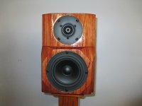
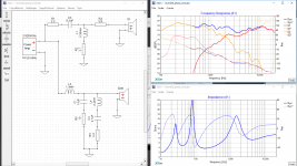
So the question to ask is why would you pay extra for Seas Excel or ScanSpeak stuffs? I did a simple calculation as for the cost and my Nextel/AirCirc is about $1.2K and the SB Poly pair here is about $380. That is a big difference. So what is the real difference? After listening, I mean the SB poly just do not have the sophistication of the Nextel. The Nextel midrange just washes over you whereas the SB poly is a bit dry and somewhat distant. The depth is somewhat truncated. Sort of reminds me of hearing Salma Hayek speaking English vs. Uma Thurman. If the SB poly was the only thing I listened in my life I suppose I would be happy but unfortunately I did listen to the Nextel so you could say my life will forever be cursed.
Vertical displacement is the prerequisite, then phase offset determines the exact geometry of the XO-induced lobing. Plus there is lobing from the drivers all by their own when operated above ka=1, lobing from the baffle, etc.Lobing is cause by physical displacement, not phase differences.
The plot in #43 is actually quite good I would say.Just an observation here: in almost every plot in this thread the drivers are not very well time/phase aligned.
At least we have symmetric lobing and at no angle the response is louder than on-axis. With large vertical offset the first nulls may be located at rather narrow angles, though.The problem with designing a speaker with non-zero phase alignment (such 90deg for odd order filters) is that the frequency response varies more rapidly as you move off axis. I.e. you change from a sitting to standing position and get blasted with +3dB at the XO, or you sit too low/close and a deep null appears. If you design for perfect phase alignment you'll find that the speakers will be much more enjoyable to listen to because they won't demand a 'head in a vice' listening position - you can move around and they still maintain a flat response.
Time alignment (=physical displacement) and phase shift are one and the same thing. Phase shift is just frequency dependant time shift and vice versa.Lobing is cause by physical displacement, not phase differences.
If you design for 0deg phase difference between the drivers in the listening axis then as you move off axis in either direction you only get a mild null. At some angle off axis you achieve 90deg phase misalignment equalling -3dB system response and moving even further off axis 180deg misalignment giving a deep null. Hopefully if you designed things right by choosing appropriately sized drivers and crossover points only impractical listening positions will achieve a serious null or lobing (multiple nulls).
Starting at non-zero phase alignment in the design axis handicaps the off axis response because the same amount of change in phase (or displacement since they are proportional) equals a much larger change in amplitude. Going from 0deg to 45deg gives -0.7dB. The same 45deg shift but from 90deg to 135deg gives -5.3dB. You will also sooner reach 180deg in such a system giving a deep null.
Going from 90deg alignment back to 0deg (moving off axis in the other direction in a system designed for 90deg alignment) gives +3dB which is subjectively more noticeable than -3dB.
Last edited:
I still don't agree. Consider a co-axial. A phase difference will sum to less than 6dB but it isn't going to create nulls around a lobe.(=physical displacement) and phase shift are one and the same
Usually this is the floor and ceiling. Sometimes these surfaces have absorption applied to them. Sometimes the speakers use directivity to avoid these. These surfaces do more than just add to the sound. But either way, the power needs to be measured to remove the guesswork.only impractical listening positions will achieve a serious null or lobing
Concentric/coaxial two-way radiator has minimal physical "time shif" or physical path lenght difference in all directions (or practically in two x/y dimensions) They still might have electrical acoustic phase difference, but it remains constant also off-axis.
Here is a good lesson
Typically we have two radiators is same frontplate, with some distance between them in x/y an perhaps also z dimension. Then things get much more complicated and are dependant on offset angle, direction, separation distance and frequency/wavelength. Typically drivers are set in-line vertically, then horizontally they hold the electrical phase difference at different angles, but in vertical offset, the relative pathlength difference chances, and thus summation changes (we get lobing in response) because the relative difference of phase angles changes! (This is tricky to put in words...)
In simulations we usually see only one frequency, the xo point. The shape of lobing depends on xo topology. XDir is a nice simulator to study this (in 2D)!
Last edited:
- Status
- This old topic is closed. If you want to reopen this topic, contact a moderator using the "Report Post" button.
- Home
- Loudspeakers
- Multi-Way
- First order vs. First order time-aligned and a dilemma