Hi MikkoThis will not be a detailed report but after hearing FO 1,3 in 2 high quality system I can say you get insane value for your cash.
...
Enjoy the music
Peace,
Mikko
Agree, First One v1.3 amplifier module will set new standard for low cost modules on the market. The v1.2 to v1.3 upgrade documentation is in preparation and will be send to the owners of ready made First One v1.2 amplifiers.
Kindly ask to send your requests for an upgrade documentation accompanied with some pics of ready made amplifiers to:
first.one.amp@gmail.com
Next week First One amplification (two amps and preamp) will be a part of the system attending Zagreb Hi-Fi Show. Short report follows soon.
L.C.

Is FO V1.3 available? As completed, tested pcb boards
Thank you
No, not yet. We'll start with upgrading procedure first and later on offer ready made v1.3 First One modules. In this way all present owners will get time and opportunity to get leveled on current version.
Hi!
I am asking for help.
I need amp something between 60-80W. Is it possible to configure FO to that power?
Thank you!
Yes, just supply them with SMPS1200A180 and power level would be as requested.
")
Two options:
- resistors devider in front of the input ie. 1 k + 1 k devider will decrease gain by -6 dB, so the complete voltage gain will be +21 dB
- solder 1,5 k (2010 SMD case) resistor parallel to R5, R6 and 1,5 k (2010 SMD case) resistor parallel to R7, R8, thus reduce gain by -4 dB, so the complete voltage gain will be +23 dB
Of course by different resistors values (in both options) you could get any gain reduction needed. First option is easier to realize but it will significantly reduce input impedance.
maybe with 10k+10k input impedance will not be reduced that much?
LC ,
I'm curious about your pre. Will it fit in the FO chassi?
I'm asking because a friend of mine is looking for a integrated amp.
I remember reading about in this thread, but I'm to lazy to check the whole thread again.
I guess I'll have to change my nick to something including" lazy ". (-;
I'm curious about your pre. Will it fit in the FO chassi?
I'm asking because a friend of mine is looking for a integrated amp.
I remember reading about in this thread, but I'm to lazy to check the whole thread again.
I guess I'll have to change my nick to something including" lazy ". (-;
Of course, but the input low pass filter capacitance has to be changed, then.maybe with 10k+10k input impedance will not be reduced that much?
An other solution should be to double the value of the emitter resistances of the input transistors, to add ~6DB of global feedback ?
But i don't see the need, i would prefer to add a passive attenuator to my tweeters, with accurate zobel, if i was in this position.
Last edited:
Of course, but the input low pass filter capacitance has to be changed, then.
An other solution should be to double the value of the emitter resistances of the input transistors, to add ~6DB of global feedback ?
But i don't see the need, i would prefer to add a passive attenuator to my tweeters, with accurate zobel, if i was in this position.
i have plenty of adjustments from the electronic crossover.
the reason is i want to lower the gain is because a hiss is barely audible and
i can easily eliminate it since know it,s adjusted at -7.5db.
p.s. the zobel is in plans but i need to figure out how to calculate it.
Yes think so, best the signal level thru cable is as high as possible and impedance as low as possible then the noise induced if any is small compared to signal level and the lower impedance is better to fight thru cable evils capacitance and induction...........maybe it,s better to place them at the amps inputs (after the interconect cables)?
The standard mini dsp 2x4 data is 560ohm output impedance, maybe better to run two 5,6K or 10K, and then make the input low pass filter cap relative same smaller value, as Esperado mention in post #1486.
Maybe try the trial version of "WinspeakerZ" from www.trueaudio.com, don't think it's time limited the limit is running only one driver which we will not do for this calgulation. I hold the licensed version and under menu "Crossover" you can calculate both "Inductance compensation" and also "Resonance compensation". If you want to check and measure the precision of compensation www.intertechnik.com distribute Dayton Audios USB DATS unit which can do impedance plots for drivers boxes/ports capasitor resistors and inductors + measuring value for capasitor resistors and inductors. You can also measure the impedance with you soundcard in REW see the help file how to setup, though i recommend not use your primary expensive sound card but a second hand cheaper one because heard of broken soundcard input after such a sweep...........p.s. the zobel is in plans but i need to figure out how to calculate it.
Yes think so, best the signal level thru cable is as high as possible and impedance as low as possible then the noise induced if any is small compared to signal level and the lower impedance is better to fight thru cable evils capacitance and induction.
The standard mini dsp 2x4 data is 560ohm output impedance, maybe better to run two 5,6K or 10K, and then make the input low pass filter cap relative same smaller value, as Esperado mention in post #1486.
i am a bit confused.
the higher the resistors the lower the low pass frequency?
where is it set without resistors?
i am a bit confused.
the higher the resistors the lower the low pass frequency?
where is it set without resistors?
At 2,34 MHz/-6 dB
1-1,5 k could not degrade the sound because of input filter change, it's just set too high. Maybe is the output impedance of your DSP.
Try two 4,7 k and check.
At 2,34 MHz/-6 dB
1-1,5 k could not degrade the sound because of input filter change, it's just set too high. Maybe is the output impedance of your DSP.
Try two 4,7 k and check.
thanks i wil.
Found a movie on YouTube where one can visual see how input low pass filter can change amps specs, link: Volume reg problem - YouTube
sufficient heatsink?
While shopping for case metalwork, I find a dearth of thermal specs for the heatsinks that accompany the casework.
Does anyone here have a clue as to whether or not these common configurations would be sufficient for a FO module?
All are black anodized aluminum:
Radiator size: 300*70*50mm, Base plate thickness is 10mm, 28 fins
Radiator size: 300*90*50mm, Base plate thickness is 10mm, 28 fins
Radiator size: 300*115*50mm, Base plate thickness is 10mm, 28 fins
Looking forward to listening... thanks!
Agree. To have ratio 1/10 output z to input z use two 3,3K for 5,78K input, or as LC write try 4,7K and check.if i calculate correct it sees 2800ohm now.
mini dsp is 560ohm output so there is a problem.
By looking at post #1 i see R1 at 0,68K and adding new 3,3K is 5,85 times more, If you like to keep RC input filter same low cut make the capasitor that probably sits at soldering side of PCB 5,85 times less value. I haven't got FO modules but have LC's VSSA GB module and there input RC filter was 680ohm/100pF, in this case it would be ~18pF or 22pF instead of the 100pF.
While shopping for case metalwork, I find a dearth of thermal specs for the heatsinks that accompany the casework.
Does anyone here have a clue as to whether or not these common configurations would be sufficient for a FO module?
All are black anodized aluminum:
Radiator size: 300*70*50mm, Base plate thickness is 10mm, 28 fins
Radiator size: 300*90*50mm, Base plate thickness is 10mm, 28 fins
Radiator size: 300*115*50mm, Base plate thickness is 10mm, 28 fins
Looking forward to listening... thanks!
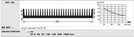
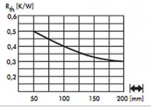
Download the catalogue from fischerelektronik: Catalogue - Fischerelektronik
Find an equivalent heatsink (or as close as possible). You will find the C/W dissipation curve as a function of heatsink size.
Heatsink guideline
Great... thanks... looks like even a 300mm L * 60mm H * 40mm D would meet spec, so any of the three should work?
Cheers
Download the catalogue from fischerelektronik: Catalogue - Fischerelektronik
Find an equivalent heatsink (or as close as possible). You will find the C/W dissipation curve as a function of heatsink size.
Great... thanks... looks like even a 300mm L * 60mm H * 40mm D would meet spec, so any of the three should work?
Cheers
Attachments
Last edited:
Great... thanks... looks like even a 300mm L * 60mm H * 40mm D would meet spec, so any of the three should work?
Cheers
Well, I don't have practical experience. I would probably just want to be on the safe side and order larger ones.
Where are you sourcing the heatsinks? I am looking at the largest size heatsink from HeatsinkUSA in 4" or 5" height. Those are shorter but the fins are longer
- Home
- Vendor's Bazaar
- First One - mosFET amplifier module