Given that breakdown, I should be expecting to pay £100 all in! I was expecting the dual monos to cost around £200 (and would have if I'd gone for cheaper cases). I guess that the cheap cost of the LM3886 amp needs to be factored into your breakdown...I'd say reduce the percentage contribution of the amp to 15%.AndrewT said:expect ~30% for the amplifier, another ~30% for the chassis and heatsinks, another ~30% for the PSU and ~10% for case hardware.
Incidentally, care to recommend a discrete design for future consideration?
Decibel Dungeon recommend that one
Place a small Class X1 rated capacitor (around 0.1 uF /275 volts is fine) across the switch contacts. This will help protect the contacts from arcing and also stop them from making a noise when the switch is operated. This is optional but recommended.
I trying to find something of Mouser that I can use for this but seems unable to find anything. I'd be grateful if someone could point me in the right direction.
Hi,
don't go abroad (Mouser) for this standard readily available component.
X1, X2, Y1, Y2 capacitors are standard fare here in the UK.
Look at RS, Farnell, Rapid etc.
You can also look for the integrated R+C snubber (suppressor) designed specifically to suppress interference emanating from noisy equipment.
Thanks Andrew, I'll take a look.AndrewT said:Hi,
don't go abroad (Mouser) for this standard readily available component.
X1, X2, Y1, Y2 capacitors are standard fare here in the UK.
Look at RS, Farnell, Rapid etc.
You can also look for the integrated R+C snubber (suppressor) designed specifically to suppress interference emanating from noisy equipment.
I'm in the process of building a power supply light bulb tester. I've got my bits from Maplin. However, I didn't like the look of their push to make switches for two reasons.
Firstly, they came with tiny solder lugs and I wanted to use insulated crimps and secondly because I wouldn't be able to tell by looking at the switches if they were switched on or off.
So I got these illuminated rocker switches instead (GU55 & GU56). clicky
These switches have four quick connect lugs. Anyone know how I should connect these up? They have no markings whatsoever.
I have used similar switches and they did come with numbers next to the connectors. Well-hidden and hard to read they were.
In the link's picture, the connector between the two plastic separators is either phase or neutral. The connector to the right is the corresponding output. On the side that is hidden in the picture the same thing, the connector between the separators in phase or neutral, the one in the corner is output. The light is connected between the two output connectors and lights up, when the switch is on. Polarity does not matter.
In the link's picture, the connector between the two plastic separators is either phase or neutral. The connector to the right is the corresponding output. On the side that is hidden in the picture the same thing, the connector between the separators in phase or neutral, the one in the corner is output. The light is connected between the two output connectors and lights up, when the switch is on. Polarity does not matter.
PJPro said:I'm in the process of building a power supply light bulb tester. I've got my bits from Maplin. However, I didn't like the look of their push to make switches for two reasons.
Firstly, they came with tiny solder lugs and I wanted to use insulated crimps and secondly because I wouldn't be able to tell by looking at the switches if they were switched on or off.
So I got these illuminated rocker switches instead (GU55 & GU56). clicky
These switches have four quick connect lugs. Anyone know how I should connect these up? They have no markings whatsoever.
i've looked at the decibel dungeon site as i too am making the bulb tester.
I have a few questions that are bugging me.......
The bulb is put in series on the live ? with the neutral not directly involved.
Why use different wattage bulbs when testing ?
can anyone explain how it works, as i like to learn.
")
Hi,
search bulb tester on this Forum.
A low wattage bulb is required to current limit a low wattage piece of equipment.
Using that same low wattage bulb on a higher wattage piece of equipment will cause the bulb to glow or maybe even go full on.
That will prevent a good circuit from reaching full mains input voltage.
You start with a low wattage bulb and prove to yourself that you have no catastrophic wiring errors.
Gradually increase the bulb wattage to suit the load that you are testing.
If one uses a high wattage bulb, say 150W, to power up a small pre-amp, then there is a good chance that you could seriously damage the pre-amp due to the current limiting action of the bulb tester being too high.
Do NOT try to bias up a ClassA Power Amplifier through the protection bulb tester.
Do NOT try to bias up a high bias ClassAB Power amplifier through the protection bulb tester. By high bias I mean Iq>=40mA.
The bulb holder is wired into the Live line only.Ted205 said:The bulb is put in series on the live ? with the neutral not directly involved.
The Neutral and the Earth (PE) pass straight through from Plug Top to Socket Outlet.
You do not need either of the switches included in the deluxe version shown in DD site.
If the bulb is wired in series with the Live as it should be, all current must pass through the bulb. At low current, the filament will not heat much, and resistance will be low. As current rises, the filament heats, and resistance rises. It acts as both a current limiter and a warning device (if the bulb is full on, there may be a short). This protects your equipment (and you!) while allowing you to check voltages.
Look for X2, e. g. WIMA MP3. The ones Andrew mentioned with the integrated resistor come from RIFA.PJPro said:Incidentally, I've tried sourcing these X1 caps with no luck.
LM1875 power
Go to www.MPJA.com for good trannys or better yet Apex jr.com. I have used units from both with success and the price is right!! I use 12 volts on my computer setup and it is far more than adequate.
Go to www.MPJA.com for good trannys or better yet Apex jr.com. I have used units from both with success and the price is right!! I use 12 volts on my computer setup and it is far more than adequate.
pacificblue said:I have used similar switches and they did come with numbers next to the connectors. Well-hidden and hard to read they were.
In the link's picture, the connector between the two plastic separators is either phase or neutral. The connector to the right is the corresponding output. On the side that is hidden in the picture the same thing, the connector between the separators in phase or neutral, the one in the corner is output. The light is connected between the two output connectors and lights up, when the switch is on. Polarity does not matter.
I'm still not sure I understand how to connect these up. I have produced a picture (see below). I think the illuminated switch on the left is OK. But I can't fathom how to wire in the one on the right.
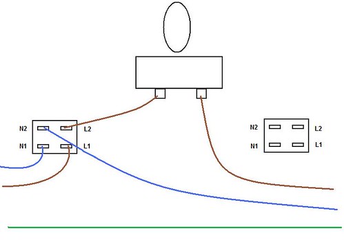
Sorry if it's really obvious, but I'd be grateful for a steer in the right direction.
Yes.PJPro said:I think the illuminated switch on the left is OK.
What is it supposed to do that the one on the left does not already do?PJPro said:But I can't fathom how to wire in the one on the right.
- Status
- This old topic is closed. If you want to reopen this topic, contact a moderator using the "Report Post" button.
- Home
- Amplifiers
- Chip Amps
- First Lm3886