heres the regulated psu from nuuks site - http://myweb.tiscali.co.uk/nuukspot/decdun/gc/snub.reg.psu.png
one thing you should included is fuses. Ideally one before the transformer and one on the power rail after the PSU to protect the amp.
Personally i use a fuse on the power rail (both +ve and -ve) and the Power Gnd rails (+PGND, -PGND) coming from the PSU to protect against reverse polarity (which is easy to do when modifiying the circuit).
Hi,
fuse the mains side - definitely.
Keep the mains fuse as low as possible - preferable. This requires some form of soft start.
Use a bulb tester on the mains input.
The PTC of the bulb filament gives automatic protection to the downstream circuit, even wiring faults on the mains side of the transformer and reversing the PSU to amplifier connections.
PJPro said:
Do you think that my two 160VA transformers will be under powered?
I've fantastic results with 2x120VA and chipamp.com power supply modules. If you're doing dual-mono, 160VA per channel should be very solid.
agreed.Atilla said:I've fantastic results with 2x120VA and chipamp.com power supply modules. If you're doing dual-mono, 160VA per channel should be very solid.
If you want 60W + 60W from a two channel amplifier, then generally one will find that a transformer rated from 120VA to 240VA will work well, i.e. VA ~ one to two times the total maximum output power.
Atilla said:
I've fantastic results with 2x120VA and chipamp.com power supply modules. If you're doing dual-mono, 160VA per channel should be very solid.
Result! That's good to know.
I've really been sweating over transformer selection and ended up just getting them. They arrived the other day and look pretty impressive. And they're soooo heavy so must be high quality!
") I went for the fully potted/encapsulated ones from RS. Cost almost as much as the dual mono kit from chipamp.com. Still....
I went for the fully potted/encapsulated ones from RS. Cost almost as much as the dual mono kit from chipamp.com. Still....Ya know, I made the changes to my schematic and spent some time looking at....feeling that something was not quite right. I finally realised that it was the schematic from chipamp.com that was incorrect. Perhaps I'm learning something?PJPro said:
Gotcha. It's my schematic that's wrong. I was comparing the schematic quadtech posted with the chipamp.cpm schematic.
I'll revise mine and repost.
Thanks
I have swopped around C6 and R4 on my schematic and will resubmit shortly.
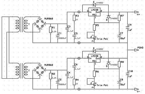
Well, don't forget this is about extending the PSU as supplied by chipamp.com where the snubbers are already present.Ted205 said:c6 & r4 is the snubber network and is commonly put at the output of the power supply i.e after c10
The bolt on bit is to the right of C5/R3 and C6/R4. The end of the chipamp.com PSU is represented by the circular features on the rails and PGNDs. The stuff to the right of these features has been lifted from the application notes for the chip.
Clearly, if one were designing this from stratch, a different approach would be taken.
AndrewT said:Hi,
what does the 338 datasheet have to say about fitting capacitors close to the input and output pins of the regulator?
Extract from the National LM338 webpage.....
Normally, no capacitors are needed unless the device is situated more than 6 inches from the input filter capacitors in which case an input bypass is needed. An output capacitor can be added to improve transient response, while bypassing the adjustment pin will increase the regulator's ripple rejection.
I'm hoping to bypass all of this agro by simply sticking to 8 ohm speakers if I can. But an interesting diversion anyway.
I think I've decided on the cases I'm going to get; a couple of the Galaxy Maggiorato with the 10mm black front panel at 330mm by 170mm. Trouble is that these aren't cheap at around £100 delivered.
Taking to account the cost of the kit (£67), the transformers (£65), the cases (£100) and the extra bits and pieces (£70), it's all looking a bit expensive at around £300 all in.
On top of this, if I build an Aikido based preamp using two of the same cases above, I reckon the total cost of power amp and preamp will be upwards of £600. This is getting into serious kit territory...with a Naim Nait 5i coming in at only £765.
Clearly, there isn't the same level of satisfaction involved in just buying a commercial amp...but the commercial kit does have resale value.
Do you think that the chip amp dual mono power amps and an Aikido preamp is going to be in the same territory as the Naim Nait in terms of sound quality? I'd be grateful for a little reassurance at this point.
I am very much biased in favour of good discrete designs.PJPro said:Do you think that the chip amp dual mono power amps and an Aikido preamp is going to be in the same territory as......... in terms of sound quality?
Look at the amplifier cost (£67) compared to the total budget (£600).
Double the amplifier cost, nay go the whole hog and triple the amplifier cost.
Spend £200 on a very good discrete amplifier and you will not regret it.
But, first build your chipamp without all the expensive add-ons and have a listen.
OK. I've learnt something else. I though the snubber caps actually sat around the rectifier.Ted205 said:c6 & r4 is the snubber network and is commonly put at the output of the power supply i.e after c10
If you look at the schematic for the TREAD
here
I thought the snubbers were C1 to C4. But it seems that these are simply to suppress noise around the bridge and are optional.
Why haven't I seen any other schematics which use this approach?
And that is, what a snubber is for, to suppress noise.PJPro said:I thought the snubbers were C1 to C4. But it seems that these are simply to suppress noise around the bridge and are optional.
You will see more of these and of similar, slightly different setups as well. Some use less capacitors, others add resistors in series to them, then again different values are used up to 100 nF. In many cases the caps are also omitted. That depends on the circuit, the type of rectifier, the layout and the skills of the designer.PJPro said:Why haven't I seen any other schematics which use this approach?
The amplifier cost is actually less than that. The bulk of the £67 is probably spent on PSU PCB and components.....so the amp probably comes in at about £25.AndrewT said:I am very much biased in favour of good discrete designs.
Look at the amplifier cost (£67) compared to the total budget (£600).
Double the amplifier cost, nay go the whole hog and triple the amplifier cost.
Spend £200 on a very good discrete amplifier and you will not regret it.
But, first build your chipamp without all the expensive add-ons and have a listen.
One of the reasons I'm going for the slightly larger case is that it will allow me to change the amplifier at a later date. Clearly, there are a number of options. I could use multiple LM3886's as many others seem to have done. Or one could go discrete. I'm not sure if my transformer would support the former but it might support the latter.
I have had a go at discrete circuits in a limited way (see here) and enjoyed the experience. But yes, I'll build the chip amps and see what I think. Will the result be comparible to the Naim Nait?
Clearly, these boxes can be recycled for subsequent builds and hopefuly are big enough to accomodate different design options.PJPro said:Well, I've taken the plunge and bought the cases. I went for the 330mm x 230mm in the end. With the 10mm thick front panels and 8 feet, the total cost, including VAT and delivery was £130.94. Gulp!
- Status
- This old topic is closed. If you want to reopen this topic, contact a moderator using the "Report Post" button.
- Home
- Amplifiers
- Chip Amps
- First Lm3886