yes, yes, yes!!!Redshift187 said:If you do not use DC blocking capacitors at any point in your setup, use a DC detection and protection circuit on the output!
FWIW, Jaycar Electronics has one of these in kit form (I have one built up but haven't used it yet). I think you have Jaycar over there nowadays...
It has DC detection, over-temperature detection and an AC sense circuit to detect power-up and power-down to disconnect the speakers instantly. However, the board is quite big...around 100 x 80 or so (est.).
I'm using it in my second SKA chassis along with a home built soft-start on perfboard.
Stuey
These are available in the UK, I have never used them mindst. Others seem to like them by the look of things.
http://www.esr.co.uk/velleman/k4700.htm
John
http://www.esr.co.uk/velleman/k4700.htm
John
As I say, I have no experience with that kit.
I have put a couple of Velleman kits together in the past and had no problems with them, the boards are nice to work with.
They use "Euro" pictorial style instructions, but if you follow the pictures and check the parts values before soldering them in they are fine.
It was a Velleman mono amp kit that first brought me to this website. Maplin sold me the kit and then had no idea about a suitable transformer or heatsink, or where to get one.
I'm still waiting for their Customer Services Department to reply to my question some 4 years later! Needless to say I buy my stuff elsewhere these days.
John
OK. I have been looking at the chipamp schematic. This is available in the manual on page 8. It looks to me that one part of the high pass filter is already present i.e. R2. So, maybe I just need the cap?
I have implemented the feedback capacitor option, which is supposed to lower DC offset. I assume this is regarded as inadequate.
I have implemented the feedback capacitor option, which is supposed to lower DC offset. I assume this is regarded as inadequate.
PJpro
Are using a volume control somewhere else or add one here? It will affect the input filtering
Output RF intrusion can be seen on ESP Fig 2 = L1+R5
http://sound.westhost.com/project19.htm
Input RF bypass cap can be added across R1 looking at ESP fig 2
use 220pF 2.5 mm lead spacing also input ferrite beads are nice as well but not mandatory.
Input DC block see ESP fig 2 and writeup
Input Ground loop isolation use series 120 ohm 1/8 Mtl film bottom of R1 to RCA input outer conn. ( then u can delete the other controversial big clingon parts bridge with a wire)
Don't really need slow start for this VA power esp using 230VAC (I have used 700VA toroids at 120VAC w/o problems for years) You won't blow fuses unless they are rated too close.
Use what the manual says for 120 AC fusing divided in half for 230VAC.
Hi Pj,
the manual says use a slow blow 2A fuse to prevent blowing on start up.
Don't follow this advice.
A T2A will pass ~4A for many seconds and maybe extend to minutes.
In event of a malfunction or accidental abuse that T2A will provide the effective heating power of 1kW until it blows.
That is inviting trouble when a 160VA does not need such a fuse to run properly.
Close rate your fusing to suit the normal operational conditions and ignore all this other advice on fitting big fuses to suit the few milliseconds of start up condition.
If close rating causes nuisance blowing with your transformer then add on a delayed bypass soft start.
BTW,
I seem to remember someone giving you advice on how to implement the RF filtering.
If you only rely on primary fusing of a transformer, you should absolutely fit a soft-start circuit. There is no way you can achieve adequate overload protection without one.
The only way to skip the soft-start circuit is to use correctly sized fuses on the secondaries, which provide the overload protection. Then the size of the primary fuse becomes less critical, because they only need to provide protection from shorts. When transformer manufacturers recommend a fuse rating for the primaries, they assume that fuses for the nominal current rating are fitted to the secondaries.
The only way to skip the soft-start circuit is to use correctly sized fuses on the secondaries, which provide the overload protection. Then the size of the primary fuse becomes less critical, because they only need to provide protection from shorts. When transformer manufacturers recommend a fuse rating for the primaries, they assume that fuses for the nominal current rating are fitted to the secondaries.
pacificblue do you mean placing a fuse on the secondaries before the bridge rectifiers ?
or is after the psu on the DC rails ?
or is after the psu on the DC rails ?
Hi,
placing secondary fuses before the smoothing capacitors does almost nothing to improve safety. They have to be rated to survive repeated initial charging of the smoothing capacitors and this requires them to be T type and about two to four times bigger than necessary.
If one wants to improve safety the secondary fuses must be placed after the main smoothing capacitors and then close rated to suit the loading and the amps ability to drive that load when NOT abused.
The secondary fuses go directly behind the transformer, before the rectifier. If you put them after the rectifier, you get another short-circuit protection, but no overload protection for the nominal rating of the transformer.
If the secondary fuses blow during initial capacitor charging, the transformer is too small for the smoothing capacitance.
There is an example in Douglas Self's "Audio Power Amplifier Design Handbook". In the fourth edition it is figure 8.1 on page 243 with the corresponding chapter "Fusing and rectification" that starts on page 244. The way it is shown there is in line with the way transformers are protected in my field of work.
Self also recommends not to choose the fuse rating too close to the actual current consumption, because "a fuse operated anywhere near its nominal fusing current has a short life-time, due to heating and oxidation of the fuse wire." (page 401 in that book)
Again, thanks for all your comments guys. Really appreciate your support.
So, summarising my understanding of all of the above......
Fusing
1 amp slow blow fuse in the power inlet module.
This is a bit higher than Andrew recommended but follows the advice of Douglas Self kindly provided by pacificblue. Unfortunately, I've already bought 2A fuses following the advice of the Chipamp.com manual. I also bought some 3A as well. Guess I need to get some more.
I'm going to skip the fuses on the secondaries, unless I'm making a big mistake in doing so.
Soft start circuit required.
This is an unforeseen addition. I hoped this was simply going to be a relay and a few resistors (as per the schematic above). Looks like it's going to be something more complex.....and I'm rapidly running out of space in my case. I took at look AMB's Epsilon 12 (which is nice and small) but it isn't recommended for power amps. I'd be grateful if someone could point me to the most basic possible soft start schematic so I can consider my options.
RF filtering & DC offset
I think what we are saying here is place a cap on the signal input. ESP recommends a 3.3uF cap. The resistor (R2 - 22K) is already in place. The provision of the cap, in addition to the resistor, provides high and low pass filtering. The cap also counters DC offset.
It is also recommended that RF filtering is applied to the output by applying a 10R resistor and L1. Can someone tell me what L1 is? The symbol on the schematic is new to me and it's not mentioned in the text.
I'd be grateful for any corrections to the above where I have misunderstood. This time I'll wait a bit before rushing out and buying the stuff. 🙂
What I will say is that I might have been better off buying my kit from ESP rather than chipamp.com. It seems there is so much more to put in place than is suggested by the chipamp manual.
infinia said:PJpro
Are using a volume control somewhere else or add one here? It will affect the input filtering
No, I wasn't intending to provide a volume control on the power amps. I hoped to use the variable line out on my Beresford DAC/preamp.
Well, the ESP Soft Start PCB seems like an option.....although unless the transformer is extra small, I can't see how I'm going to get it all in the case!
BTW, here's a picture of one of the amps
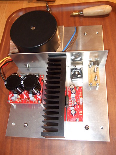
I'm deeply unhappy with my implementation of the disconnecting network (the proto board with the bolts). I'm gonna have to think again.
BTW, here's a picture of one of the amps
I'm deeply unhappy with my implementation of the disconnecting network (the proto board with the bolts). I'm gonna have to think again.
The soft start in that link looks pretty nice. Note though that it says max continuous current is 6A.
Sorry 3.3uF cap is NOT a lowpass at RF
Andrew just because it has a SRF doesn't mean it stops RF above it. Are you an expert at RF design now and have you ever seen a network analyzer , let alone used one? An experiment- stick one of those caps inline to a radio receivers antenna, still lets RF in don't it. Sir your air of authority is a sham for those that know better. (once again) The fact that you'd even suggest such a thing... nothing you'd say after the fact could save your RF job with me. EDIT> can't leave you without the fix... The solution is a series ferrite bead and a 220pf shunt cap 2.5mm LS. Now try that after the first experiment above.
PS did you ever look into the mechanics and solutions to audio ground loops. retorical question.
PJpro Good luck with your project! I like your chassis esp the nice IEC inlet module, too bad it's in back out of sight.
The DC block cap is a good idea but it'll never work for a RF bypass or a lowpass filter. RF cuts straight through a large foil cap like a hot knife thru butter. The size of the series DC block cap wouldnt do a thing for RF design, either series or shunt.AndrewT said:PJ,
the input filtering does two different things.
The high pass filter determines the low frequency foll off and also blocks DC from the source, if any.
The low pass filter determines the high frequency roll off and also attenuates RF/interference coming in through the interconnect or from a source.
So the 4 components needed at the input do in total four jobs. Can't ask for better value than that.
If you know that all your sources can NEVER pass DC on to the next stage, you can delete the DC blocking capacitor from the power amp input. But you still need to determine the low frequency roll off of the amplifier.
The choice becomes yours once you have informed your self of the way your sources and your power amp interact.
Andrew just because it has a SRF doesn't mean it stops RF above it. Are you an expert at RF design now and have you ever seen a network analyzer , let alone used one? An experiment- stick one of those caps inline to a radio receivers antenna, still lets RF in don't it. Sir your air of authority is a sham for those that know better. (once again) The fact that you'd even suggest such a thing... nothing you'd say after the fact could save your RF job with me. EDIT> can't leave you without the fix... The solution is a series ferrite bead and a 220pf shunt cap 2.5mm LS. Now try that after the first experiment above.
PS did you ever look into the mechanics and solutions to audio ground loops. retorical question.
PJpro Good luck with your project! I like your chassis esp the nice IEC inlet module, too bad it's in back out of sight.
Infinia, that was completely uncalled for. Your quote from AndrewT did not even have in it what you are claiming he said. He said the low pass filter, not the DC blocking capacitor. AndrewT often recommends a 220pf cap for RF filtering. Now stop polluting this thread with your bickering.

- Status
- Not open for further replies.
- Home
- Amplifiers
- Chip Amps
- First Lm3886