Complete Balderdash Andrew. Using best approved construction methods is completely safe. The china syndrome circuit adds costs without any safety or performance improvements.
Hmm... now we are resorting to name calling (technical arguements are failing then)
PS I'm just making fun of the china syndrome network not you Andrew... don't take things so personal.. When you get far out on a limb it's OK just to let go/
Hmm... now we are resorting to name calling (technical arguements are failing then)
PS I'm just making fun of the china syndrome network not you Andrew... don't take things so personal.. When you get far out on a limb it's OK just to let go/
What you call 'China syndrome circuit' is standard on many amplifiers. Especially PA amplifiers are often equipped with it. You will see it in the schematics from Bryston to name just one renowned manufacturer.
By the way, the switch does not convert the amplifier from Class I to Class II or vice versa. It remains Class I in either switch position. Class II equipment has no direct PE connection and is what you usually get, when you buy off-the-shelf. ClassII is no option for DIY, because 98 % of DIYers cannot build it and the remaining 2 % cannot make the necessary tests to confirm Class II compliance.
It is in the nature of Class I devices that ground-loops can ocurr, when the device is connected to another Class I device or a Class II device with a connection to PE, e. g. through antennas, satellite dishes, broadcasting cable systems, etc. Therefore the ground-lift switch was invented. The combination of that with the ground-loop breaker as discussed above is a safer way to go about it than to interrupt the connection from ground to PE entirely.
If you want or need a potential earth ground, and we all should use one, then add a designated earth ground to your dwelling for your audio equipment. Using the standard in my part of the world which is a 10 foot long rod driven into the earth and tied to the ground at the electrical panel you can get a separate rod and tie just the PE grounds from your audio equipment to this.
CAUTION: This might be a good time to call a licensed electrician.
In any case I have been able to completely isolate any interference from the air conditioning system, refrigerator and all of the motors in my shop plus the flourescent lights. An added bonus is it is cheap to implement. It works very well. An added note to some. Older buildings have used the water pipes for grounds for decades. If you live in an old apartment building then ALL of the electrical devices in the structure are tied to the same earth ground. That is a huge potential for interference. A dedicated ground is better than lifting the ground. It is their to save your life. Period.
Tad
Why is the disconnecting network such an issue? It has been discussed in the past in other threads within this forum and is recommended on the Rod Elloit website. If I have no grounding hum, I'll bypass the network by closing the switch. If I do (now or later), I'll open the switch.
So. Is there a problem with the design? I'm happy to consider another way of going about this (despite the fact that I've bought the components already) and would feel more comfortable if a consensus could be reached.
So. Is there a problem with the design? I'm happy to consider another way of going about this (despite the fact that I've bought the components already) and would feel more comfortable if a consensus could be reached.
How does one go about checking what is legal?infinia said:Doesn't Rod say that the network might not be legal?
Is this legal?infinia said:I think most folks use a small resistor (47R-150R) on the RCA ground to the PCB to address ground loops/ but mostably no ground loops are to be had in a typical home setup.
I'm not trying to be difficult here. I am slightly less concerned about legality and more concerned about what is safe and what will provide the best results (sound wise).
If you go directly from the mains inlet earth to a "secured" chassis bolt is the legal/right way anything else will raise the eyebrows of any electrical inspector/examiner, then you are generally on your own from that point to convince them. That's really the first thing they look for. Sometimes they don't even like things than look like they could ever become loose and some even insist on pressfit bolts instead of screws. ( I'm speaking from experience folks ie UL listing)
OK. Well, whatever the approach to handling ground loop issues, I will make a dedicated connection to the chassis from the power inlet module.
I already have the bits for my safety earth. I went to Fasteners Network today to get all my nuts, bolts, etc. I can recommend this company to other UK DIYers. All they do is nuts, bolts and other fasteners. Find their website here.
I fairly keen on the disconnected network because I can short it out if there are no ground loop issues. Would the resistor approach mentioned have any negative affect on sound quality? Why didn't the board designer add one to the PCB? Maybe he has and I can't see it.
pacificblue said:By the way, the switch does not convert the amplifier from Class I to Class II or vice versa. It remains Class I in either switch position.
BTW Pacific the switch labeling was an inside joke> note the use of emoticon and even the added hahaha for good measure.
What you MUST have is your metal chassis connected to safety earth. That is UK law unless a device is double insulated.
To prevent problems, your RCA sockets should be isolated from the chassis. There should only be one path for signal ground.
Do NOT disconnect the safety earth from your chassis to fix hum problems. This is dangerous, illegal in the UK, and a poor fix for hum loop problems.
To prevent problems, your RCA sockets should be isolated from the chassis. There should only be one path for signal ground.
Do NOT disconnect the safety earth from your chassis to fix hum problems. This is dangerous, illegal in the UK, and a poor fix for hum loop problems.
jaycee said:What you MUST have is your metal chassis connected to safety earth. That is UK law unless a device is double insulated.
That's correct for USA as well, directly, not thru a switch or a patch of silicon. Where were the voices of reason awhile back.
Looks like there's some crossed wires developing. I can only assume this is my misunderstanding of schematic symbology. Apologies. Please let me clarify.
Here's the schematic once again.
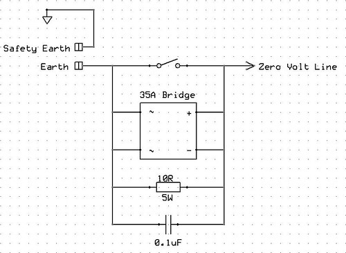
I intended the triangle in the top left to represent power ground. For me, this is the earth connection on the power inlet module.....which eventually leads to earth through my domestic wiring.
The schematic shows a wire attached to the this earth connection which runs to something I have called Safety Earth. This is attached to the chassis. No other connection is made to Safety Earth....it is a dedicated connection for the earth from the power inlet module.
There is another chassis connection called Earth. This is used to connect the Disconnecting Network to the chassis. Whether the Disconnecting Network is used or not, this connection will be used to connect the grounds from all internal circuits and sources (other than the power inlet module....which will be connected to Safety Earth).
So. The Safety Earth is not in question here. It will be in place whatever approach is used . What we are discussing is the approach to countering ground loop issues.
I have seen a number of posts which recommend that when ground loops are encountered, one simply sticks a resistor between the ground for the internal circuits and the chassis (and therefore Safety Earth). I understand that if an issue should arise, this resistor is unable to provide the protection required because it cannot handle to current involved.
The Disconnecting Network aims to address this by using a 35A bridge. In the event of a fault, yes the resistor and capacitor are probably fried. However, the bridge, with it's more robust internal linkages, will still provide a route to Safety Earth. This route is only used in the event of a fault and in the meantime, one gets the lifted ground due to the resistor and cap.
The switch is a further enhancement. It plays no role in the event of a fault....cos it will be fried. During normal operation, the switch allows the Disconnecting Network to be shorted out if no ground loop issues exist. If, however, hum is experienced, one can simply flick the switch and engage the network.
I usually prefer to be proactive.....trying to fix things before they are shown to be broken.....trying to cover all eventalities. Doubtless, this is my engineering background and engineers tend to over-engineer things.
Perhaps I am turd polishing? I'll let you decide. However, I am using this project to try and understand the issues which need to be considered when building an amp and the implementation required to address these issues (within reasonable financial constraints). If there are easier, more effective solutions (at least no worse) which provide the level of safety required, then I'm keen to hear about them.....and interested in any debate which is stimulated as a result.
Hopefully, this debate (and eventual consensus?) will help future DIYers building their first amp.
Here's the schematic once again.
I intended the triangle in the top left to represent power ground. For me, this is the earth connection on the power inlet module.....which eventually leads to earth through my domestic wiring.
The schematic shows a wire attached to the this earth connection which runs to something I have called Safety Earth. This is attached to the chassis. No other connection is made to Safety Earth....it is a dedicated connection for the earth from the power inlet module.
There is another chassis connection called Earth. This is used to connect the Disconnecting Network to the chassis. Whether the Disconnecting Network is used or not, this connection will be used to connect the grounds from all internal circuits and sources (other than the power inlet module....which will be connected to Safety Earth).
So. The Safety Earth is not in question here. It will be in place whatever approach is used . What we are discussing is the approach to countering ground loop issues.
I have seen a number of posts which recommend that when ground loops are encountered, one simply sticks a resistor between the ground for the internal circuits and the chassis (and therefore Safety Earth). I understand that if an issue should arise, this resistor is unable to provide the protection required because it cannot handle to current involved.
The Disconnecting Network aims to address this by using a 35A bridge. In the event of a fault, yes the resistor and capacitor are probably fried. However, the bridge, with it's more robust internal linkages, will still provide a route to Safety Earth. This route is only used in the event of a fault and in the meantime, one gets the lifted ground due to the resistor and cap.
The switch is a further enhancement. It plays no role in the event of a fault....cos it will be fried. During normal operation, the switch allows the Disconnecting Network to be shorted out if no ground loop issues exist. If, however, hum is experienced, one can simply flick the switch and engage the network.
I usually prefer to be proactive.....trying to fix things before they are shown to be broken.....trying to cover all eventalities. Doubtless, this is my engineering background and engineers tend to over-engineer things.
Perhaps I am turd polishing? I'll let you decide. However, I am using this project to try and understand the issues which need to be considered when building an amp and the implementation required to address these issues (within reasonable financial constraints). If there are easier, more effective solutions (at least no worse) which provide the level of safety required, then I'm keen to hear about them.....and interested in any debate which is stimulated as a result.
Hopefully, this debate (and eventual consensus?) will help future DIYers building their first amp.
Agreedjaycee said:What you MUST have is your metal chassis connected to safety earth. That is UK law unless a device is double insulated.
OK. I'll observe your advice during the build.jaycee said:To prevent problems, your RCA sockets should be isolated from the chassis. There should only be one path for signal ground.
Agreed.jaycee said:Do NOT disconnect the safety earth from your chassis to fix hum problems. This is dangerous, illegal in the UK, and a poor fix for hum loop problems.
I have tested this circuit by connecting a direct short from Live to the Disconnecting Network.PJPro said:.............one simply sticks a resistor between the ground for the internal circuits and the chassis (and therefore Safety Earth). I understand that if an issue should arise, this resistor is unable to provide the protection required because it cannot handle to current involved.
The Disconnecting Network aims to address this by using a 35A bridge. In the event of a fault, yes the resistor and capacitor are probably fried.............
......................The switch is a further enhancement. It plays no role in the event of a fault....cos it will be fried. During normal operation, the switch allows the Disconnecting Network to be shorted out if no ground loop issues exist. If, however, hum is experienced, one can simply flick the switch and engage the network.
The fuse inside the IEC socket (very similar to Pjpro's double fused version) exploded.
All other components not only survived, they all appeared to work perfectly after the test.
Had there been a switch included I would expect that to remain undamaged as well.
The switch does not need to be able the pass the kA of possible fault current. The Disconnecting Network is still in place and should be capable of doing that job,..........
The more I read Infinia's responses the more I believe he does not understand what we are talking about.
I solder the three components direct to the bottom of the rectifier spades (needs quite a bit of heat).
Bolt the rectifier to the base of the amp.
Use spade connectors to wire into and out of the rectifier and for the cross over links.
BTW,
I use 10r 600mW metal film for the resistor. 250mW would do.
Bolt the rectifier to the base of the amp.
Use spade connectors to wire into and out of the rectifier and for the cross over links.
BTW,
I use 10r 600mW metal film for the resistor. 250mW would do.
I've ordered a 5W resistor (see here) as specified in the Rod Elliot article.AndrewT said:..........
BTW, I use 10r 600mW metal film for the resistor. 250mW would do. [/B]
While I'm about it, the other components are....
35A Bridge
0.1uF Capacitor
I'm assuming that all of the above is OK.
- Status
- This old topic is closed. If you want to reopen this topic, contact a moderator using the "Report Post" button.
- Home
- Amplifiers
- Chip Amps
- First Lm3886