The document isn't written in a very comprehensible way (at least for me). I could probably explain it much easier. Things like this trick you into thinking that electronics is much more complicated than it really is. ")
How interested are you in amplifier design, what makes it tick and tick well? Just curious.
- keantoken
How interested are you in amplifier design, what makes it tick and tick well? Just curious.
- keantoken
MJL21193 said:Sometimes the problem is a good thing. I have learned something here - you are correct, it is a current mirror.
Discussion makes us dig deeper and in that we learn.
PS: But that means Dan was right - there is a CM and AndrewT didn't see it??
Hi MJL21193,
I agree. It forces one to get out the text books and reread in a different light. My references always assume "matched" transitors with identical parameters to mathmatically prove the ciruit behaves as a current mirror.
I realise one of the transistors in a current mirror is connected as a diode, but in the circuit in discussion will the parameters of transitor X and diode Y be close enough, can you consider them matched?
regards
MJL21193 said:Sometimes the problem is a good thing. I have learned something here - you are correct, it is a current mirror.
Discussion makes us dig deeper and in that we learn.
PS: But that means Dan was right - there is a CM and AndrewT didn't see it??
This is rare. Perhaps it is a success from his many efforts on increasing my understanding? You both helped me so much. I thank you both.
On this thread, I have recently conveyed information without understanding it. That's inappropriate, and I sincerely apologize.
What I saw:
Simply put, the roles of both items are the same. One of them is documented as a current mirror. Both are visually similar, in the same role, and in the same spot in the circuit. I know for sure that one of them works and I believe that the other works, and they have the same role.
This is why I think that both are a current mirror. IE: If it walks like a duck then. . . it isn't a schoolbus.
Greg Erskine said:
I realise one of the transistors in a current mirror is connected as a diode, but in the circuit in discussion will the parameters of transitor X and diode Y be close enough, can you consider them matched?
regards
Hi Greg,
I think the reasoning behind this mirror is to increase gain in the LTP without emphasis on sharing. Or at least that's what I've gotten from the discussion and the paper Dan posted.
I would like someone to jump in and explain if there is a particular advantage to this as opposed to the typical 2 T version.
keantoken said:The document isn't written in a very comprehensible way (at least for me). I could probably explain it much easier. Things like this trick you into thinking that electronics is much more complicated than it really is.
How interested are you in amplifier design, what makes it tick and tick well? Just curious.
- keantoken
Interested in amplifier design? Oh absolutely not. However, I am very interested in what it can do.
MJL21193 said:Hi Greg,
I think the reasoning behind this mirror is to increase gain in the LTP without emphasis on sharing. Or at least that's what I've gotten from the discussion and the paper Dan posted.
I would like someone to jump in and explain if there is a particular advantage to this as opposed to the typical 2 T version.
Intuition tells me. . . less ringing.
This is because, in the actual amplifier product from the 70's the passive input circuit (before the amp) that leads into it, is absolutely awful and would cause most power amps to misbehave (probably ringing midbass).
Something was responsible for the amplifier's success, and whatever it was overcame the hindrances.
In other words, this thing was fed on the audio version of poison, its nfb was compromised with a baxandall, and the amp shown still pulled off a quality performance. Hmm. . . Somewhere, there is a reason for that, and I think that you may have spotted it. I hope so. That would be cool.
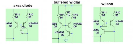
Attached here (click photo once or twice) is a short brief on this current mirror. I don't understand it too clearly, but the lights are beginning to shine through the fog. This brief is from the same document as post #13.
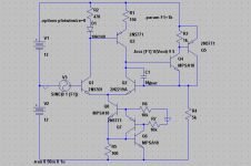
Well , the final design you choose and how simple you want it
is your choice as you will be purchasing the parts.
I was in the same stage a few months ago and opted to
use a CM on the advice of many (including D. self).
for $1.00 the whole input stage of FA1 is a deal, and not
too complex.
By MJL -I think the reasoning behind this mirror is to increase gain in the LTP without emphasis on sharing
Yes , the mirror gives 5-6db more gain allowing for a non-ef'ed
1381 (works for a mje 350 with less Re degeneration)
I've actually tried all 3 "flavors" of CM's (attachment at end)
and the board I'll make for FA1 will have pads for all 3.
OS
Attachments
homemodder said:keantoken, I could be wrong but I dont find it to affect the harmonic spectrum. I have a design which I have used for 14 odd years now which uses this in the vas and I just had a quick look at how it sims. Better THD figures using this circuit instead of mirror, by a small margin but there. Both 2nd and 3rd down. I cannot remember exactly why I chose it instead of mirror besides sounding better at high volumes. Im looking at a module now and I see that I also trim the resistor value to get exact balance. Back when I designed it it was with scope and ears.
I mean the mismatched LTP currents. If an LTP is driven too hard while it's balanced, it will spit out 3rd order harmonics. But if unbalanced, 2nd order harmonics predominate. According to what many DIY'ers say, 2nd order harmonic content is more pleasant than 3rd order.
still interesting though.
I've actually tried all 3 "flavors" of CM's (attachment at end)
and the board I'll make for FA1 will have pads for all 3.
OS
How will you decide which one to stick with?
- keantoken
keantoken said:
I mean the mismatched LTP currents. If an LTP is driven too hard while it's balanced, it will spit out 3rd order harmonics. But if unbalanced, 2nd order harmonics predominate. According to what many DIY'ers say, 2nd order harmonic content is more pleasant than 3rd order.
Hi kean,
My simulation shows a big drop in THD when using this mirror at high output, mainly in the third and higher harmonics. Interesting indeed.
It behaves differently at low output, with 3rd staying the same and the second reduced over the typical Widlar. Still, lower THD.
# 2 or 3 seem to be the top performers , if 5 cents for a resistorBy BT -How will you decide which one to stick with
is a bother # 3 is the winner with only 1 part.
Distortionwise , 2 and 3 give the lowest and best (mainly
H2) improvement. The board will allow the constructor to "play".
OS
MJL21193 said:
Hi kean,
My simulation shows a big drop in THD when using this mirror at high output, mainly in the third and higher harmonics. Interesting indeed.
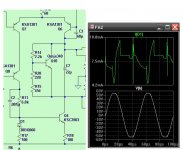
Cool. I was simming too, and I came up with this.
.0001%THD at 1KHz, 1V pk-pk.
I had a funny thought: note the different LTP devices. The 2n5769 has 1/3 the beta of the other transistor, so even though the currents are different, the base currents are the same. I wonder what would be the advantages of using different transistors in the LTP? Different transistors for NFB and input. Hmmm.
The circuit has a problem with oscillating though.
- keantoken
Attachments

Duhhh, I have been using this diode Cm for ages..
I just didn't realize it because it was being used at the
input instead of where I use it...
It does have the ability to "absorb" high order transients
and when I use it in my FA2 VAS , it kills the saturation
of the stage as well as TOTALLY eliminating H3/5.
OS
I just didn't realize it because it was being used at the
input instead of where I use it...
It does have the ability to "absorb" high order transients
and when I use it in my FA2 VAS , it kills the saturation
of the stage as well as TOTALLY eliminating H3/5.
OS
Attachments
Hi keantoken,
Matched differential pairs will always yield lower distortion as long as the circuit is designed well. Also, matching the transistors in any current mirrors will help to minimize distortion. With complimentary diff pairs, matching the beta of all four will give you lower DC offset and lowed THD.
What simulators need is a random number generator to shift the transistor parameters around with each device selected. Then you will get more realistic results. Your "matched pairs" would still have different parameters, just not as widely spread as the other transistors of the same part number. Also shift the emitter resistor values a bit. This will represent another factor that real life imposes.
-Chris
The differential pair subtracts the difference in signal between the input and output. A mismatched pair will increase distortion and DC offset voltage because the signals are not handled equally. There will be less distortion removed from the signal through the amp.I wonder what would be the advantages of using different transistors in the LTP? Different transistors for NFB and input. Hmmm.
Matched differential pairs will always yield lower distortion as long as the circuit is designed well. Also, matching the transistors in any current mirrors will help to minimize distortion. With complimentary diff pairs, matching the beta of all four will give you lower DC offset and lowed THD.
What simulators need is a random number generator to shift the transistor parameters around with each device selected. Then you will get more realistic results. Your "matched pairs" would still have different parameters, just not as widely spread as the other transistors of the same part number. Also shift the emitter resistor values a bit. This will represent another factor that real life imposes.
-Chris
anatech said:Hi keantoken,
What simulators need is a random number generator to shift the transistor parameters around with each device selected. Then you will get more realistic results. Your "matched pairs" would still have different parameters, just not as widely spread as the other transistors of the same part number. Also shift the emitter resistor values a bit. This will represent another factor that real life imposes.
-Chris
I have thought of this myself. I have no clue why it has not already been done...
- keantoken
Greg Erskine said:
Hi MJL21193,
I agree. It forces one to get out the text books and reread in a different light. My references always assume "matched" transistors with identical parameters to mathematically prove the circuit behaves as a current mirror.
I realize one of the transistors in a current mirror is connected as a diode, but in the circuit in discussion will the parameters of transistor X and diode Y be close enough, can you consider them matched?
regards
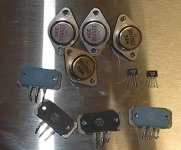
This isn't an answer, but the parts used are:
2SA798A (pair of?) for the differential amp (NEC)
2SC1328 listed as "current mirror" (NEC)
And the diode is MA150 (Panasonic MA2B150)
danielwritesbac said:
This isn't an answer, but the parts used are:
2SA798A (pair of?) for the differential amp (NEC)
2SC1328 listed as "current mirror" (NEC)
And the diode is MA150 (Panasonic MA2B150)
I have one of those dual 2SA798A and it's complimentary plus a few more nice nec devices laying around. Hard to come by.
Attachments
Thank you for being helpful Daniel.
However I'm sure those amps Ostripper posted still simulate quite well without any additions. As far as lower distortion at high power levels, I might say that it is worth using this new current mirror.
It all depends on whether you think this discussion will help you reach your goal. We could move the discussion to a new thread, if you want.
I just don't want to be wasting your time.
- keantoken
MJL21193 said:I have one of those dual 2SA798A and it's complimentary plus a few more nice nec devices laying around. Hard to come by.
Now that you mention it, I think that the actual device is not present on the real circuit board. There seems to have been a substitution. Perhaps a pair of related transistors instead of the dual?
- Status
- This old topic is closed. If you want to reopen this topic, contact a moderator using the "Report Post" button.
- Home
- Amplifiers
- Solid State
- First discrete amp, Need help with NTE 390, 391, 375, 398, and BD140, 139 project