(So as not to derail other threads nor start new threads for each question I might have, I'm going to keep updating this thread as I embark upon my first LM3886 build so it's all in once place.)
Introduction
I bought a pair of mono LM3886 kits from Analog Metric - fairly standard fair from what I can tell, a simple (& thick!) PCB with LM3886TF, Solen MKP/Nichicon FW capacitors & Dale resistors. Link: 2x LM3886 68W Power Amplifier Kit (Mono)_Solid-State Amp_Analog Metric Limited - DIY Audio Kit
My plan is to build 2 completely separate amps, by which I mean separate enclosures or 'monoblocks'. In case it's useful to know, they are each going to drive a single 8R speaker. I've built several class D amplifiers but will undoubtedly have many questions for my first 3886 build! Starting with these few...
Question - transformers & diode bridges
I recently put together a TDA8920BTH amplifier (pictures here: http://www.diyaudio.com/forums/class-d/87913-class-d-amp-photo-gallery-43.html#post2666471) For those that aren't familiar with it, the 8920 needs a dual power supply just like the 3886. I used a separate power supply board which had a single BR3510L diode bridge & 4x 10,000uF capacitors, which puts out +ve & -ve DC. The transformer I used was a 225VA job with 230V primary & 2x 18V secondaries. You can see how I wired it in the pictures in the link above.
I presumed that I could do exactly the same thing for my 3886 monoblocks, so I ordered 2x very similar transformers - 120VA with a 230V primary, 2x 25V secondaries to hopefully get about 35v out after rectification. I decided to build my own diode bridges instead of using something like the BR3510L.
Now here's where I've probably gone wrong. I assumed that the BR3510L consisted of 4x diodes inside & as it worked with my 8920 build to give me the +ve & -ve DC I needed I went ahead & ordered 4x MUR860 for each of my monoblocks. However after looking at some 3886 monoblocks from other people they all seem to use 8x diodes.
Do I need 4x or 8x? I know the choice of transformer makes a difference - the ones I've ordered have dual secondaries, which can be used independently, in series or parallel.
Question - filter caps/other power supply components
Do I need anything other for the power supplies apart from the transformers, the diode bridges & some filter capacitors? I know you can snubberize the diode bridges but I plan to try it without to begin with. I was planning on ordering 4x Nichicon KG 8200uF 50V capacitors for filter purposes - 2x for each monoblock, 1x for each rail. So each rail in each monoblock will have 8200uF of filter capacitance. Do I need anything else?
Question - heatsinking
I got hold of 2x offcuts of 6" x 3" x 3/8" aluminium angle, both 11" long & weighing in at 1.6kg each, which I plan to use as the basis for the amps. 'Open frame' style to begin with, but when I get them working I will probably close them for electrical safety. Here's a photo of one of the pieces with a LM3886TF for scale;
Here's how I'm planning to attach the components. Big cylinder is the toroid, small rectangles behind it are the MUR860 (though there might be twice as many of them!), small cylinders are the filter capacitors, amplifier PCB is at the back with the 3886 bolted to the side. The metal I got is actually larger than in this render (1" wider & 1" longer) so it'll be more spacious in reality.
I've shown a heatsink bolted onto the other side of the aluminium to the 3886 - do you think this will actually be neccessary considering how chunky the aluminium is? The amps will spend most of their lives putting out less than 5W but nonetheless I don't want their power handling to be artificially limited by insufficient cooling.
Introduction
I bought a pair of mono LM3886 kits from Analog Metric - fairly standard fair from what I can tell, a simple (& thick!) PCB with LM3886TF, Solen MKP/Nichicon FW capacitors & Dale resistors. Link: 2x LM3886 68W Power Amplifier Kit (Mono)_Solid-State Amp_Analog Metric Limited - DIY Audio Kit
An externally hosted image should be here but it was not working when we last tested it.
My plan is to build 2 completely separate amps, by which I mean separate enclosures or 'monoblocks'. In case it's useful to know, they are each going to drive a single 8R speaker. I've built several class D amplifiers but will undoubtedly have many questions for my first 3886 build! Starting with these few...
Question - transformers & diode bridges
I recently put together a TDA8920BTH amplifier (pictures here: http://www.diyaudio.com/forums/class-d/87913-class-d-amp-photo-gallery-43.html#post2666471) For those that aren't familiar with it, the 8920 needs a dual power supply just like the 3886. I used a separate power supply board which had a single BR3510L diode bridge & 4x 10,000uF capacitors, which puts out +ve & -ve DC. The transformer I used was a 225VA job with 230V primary & 2x 18V secondaries. You can see how I wired it in the pictures in the link above.
I presumed that I could do exactly the same thing for my 3886 monoblocks, so I ordered 2x very similar transformers - 120VA with a 230V primary, 2x 25V secondaries to hopefully get about 35v out after rectification. I decided to build my own diode bridges instead of using something like the BR3510L.
Now here's where I've probably gone wrong. I assumed that the BR3510L consisted of 4x diodes inside & as it worked with my 8920 build to give me the +ve & -ve DC I needed I went ahead & ordered 4x MUR860 for each of my monoblocks. However after looking at some 3886 monoblocks from other people they all seem to use 8x diodes.
Do I need 4x or 8x? I know the choice of transformer makes a difference - the ones I've ordered have dual secondaries, which can be used independently, in series or parallel.
Question - filter caps/other power supply components
Do I need anything other for the power supplies apart from the transformers, the diode bridges & some filter capacitors? I know you can snubberize the diode bridges but I plan to try it without to begin with. I was planning on ordering 4x Nichicon KG 8200uF 50V capacitors for filter purposes - 2x for each monoblock, 1x for each rail. So each rail in each monoblock will have 8200uF of filter capacitance. Do I need anything else?
Question - heatsinking
I got hold of 2x offcuts of 6" x 3" x 3/8" aluminium angle, both 11" long & weighing in at 1.6kg each, which I plan to use as the basis for the amps. 'Open frame' style to begin with, but when I get them working I will probably close them for electrical safety. Here's a photo of one of the pieces with a LM3886TF for scale;
An externally hosted image should be here but it was not working when we last tested it.
Here's how I'm planning to attach the components. Big cylinder is the toroid, small rectangles behind it are the MUR860 (though there might be twice as many of them!), small cylinders are the filter capacitors, amplifier PCB is at the back with the 3886 bolted to the side. The metal I got is actually larger than in this render (1" wider & 1" longer) so it'll be more spacious in reality.
An externally hosted image should be here but it was not working when we last tested it.
I've shown a heatsink bolted onto the other side of the aluminium to the 3886 - do you think this will actually be neccessary considering how chunky the aluminium is? The amps will spend most of their lives putting out less than 5W but nonetheless I don't want their power handling to be artificially limited by insufficient cooling.
Last edited:
You are fine with four MUR860s per transformer. You can convert your dual secondary to a center-tap secondary by connecting the two secondaries in series.
You have a super big heatsink. Great!
PS: I have a purchased (99% like yours, 1% for the different brand) from TaoBao for RMB 5.00.
You have a super big heatsink. Great!
PS: I have a purchased (99% like yours, 1% for the different brand) from TaoBao for RMB 5.00.
Last edited:
That's a relief about the diodes, I didn't want to have to pay delivery for another order just to get a few more diodes!
I figured the metal is certainly big enough, but without any fins it won't transfer the heat away to the air as fast as a smaller purpose-designed heatsink. I guess the best thing to do is try it & keep an eye on how hot the chips get.
I figured the metal is certainly big enough, but without any fins it won't transfer the heat away to the air as fast as a smaller purpose-designed heatsink. I guess the best thing to do is try it & keep an eye on how hot the chips get.
Showing the heatsink doesn't tell us about the enclosure. If this 'sink is totally enclosed it will get hot, the enclosure will need have ample vents below the heatsink and above it for best results (and to avoid creating an oven). Having the heatsink as the back of the chassis will certainly help but ideally you'd have the majority of the heatsink area external to the amp case. With vents on the top and bottom of the amp case, it could help to drill out the bottom of the heatsink so it looks like swiss cheese. You'll lose mass but gain surface area and a path for air to rise through it.
''
''
The idea is that the aluminium angle forms the bottom/side of the enclosure itself. I'll probably use a second piece of thinner aluminium angle to form the top/other-side or maybe a piece of mesh folded at a right angle.
Thinking about it I'll probably want to bolt the 3886 to the base rather than the side though - it'll be near impossible to accurately drill 4 holes for the PCB standoffs that close to the corner for mounting it to the side as the drill chuck won't be able to get in & trying to go from the other side will undoubtedly end up with them in the wrong place! It'll also allow me to rotate the PCB by 90° & use much shorter signal/output wiring.
Thinking about it I'll probably want to bolt the 3886 to the base rather than the side though - it'll be near impossible to accurately drill 4 holes for the PCB standoffs that close to the corner for mounting it to the side as the drill chuck won't be able to get in & trying to go from the other side will undoubtedly end up with them in the wrong place! It'll also allow me to rotate the PCB by 90° & use much shorter signal/output wiring.
Last edited:
Updates! But a new question (after the photos).
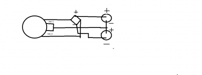
For wiring the filter capacitors (2x 8200uF Nichicon Gold Tune) I presumed I would connect the centre tap of the toroid to the -ve pin on both capacitors, connect the +ve from the diode bridge to one of the capacitors +ve pin & the -ve from the diode bridge to the other capacitors +ve pin. Not sure if this diagram will make any more sense of my explanation!
+ve --------------- +ve
capacitor
centre ------------ -ve
capacitor
-ve ---------------- +ve
However from looking at a schematic for a filter board on an auction site, it seems this would be the wrong way of doing it?
http://www.aliexpress.com/product-f...-board-for-amp-Free-shipping-wholesalers.html
Can anybody confirm how I'm meant to wire the capacitors? I don't particularly want to destroy them at ~£8 a go...
An externally hosted image should be here but it was not working when we last tested it.
An externally hosted image should be here but it was not working when we last tested it.
An externally hosted image should be here but it was not working when we last tested it.
An externally hosted image should be here but it was not working when we last tested it.
For wiring the filter capacitors (2x 8200uF Nichicon Gold Tune) I presumed I would connect the centre tap of the toroid to the -ve pin on both capacitors, connect the +ve from the diode bridge to one of the capacitors +ve pin & the -ve from the diode bridge to the other capacitors +ve pin. Not sure if this diagram will make any more sense of my explanation!
+ve --------------- +ve
capacitor
centre ------------ -ve
capacitor
-ve ---------------- +ve
However from looking at a schematic for a filter board on an auction site, it seems this would be the wrong way of doing it?
http://www.aliexpress.com/product-f...-board-for-amp-Free-shipping-wholesalers.html
Can anybody confirm how I'm meant to wire the capacitors? I don't particularly want to destroy them at ~£8 a go...
No, do not connect transformer center tap to negative terminal on both caps. Except for being unique in showing two parallel diodes per segment (per "D01" or "D02", etc) of the rectifier, the schematic you linked is correct for capacitor orientation.
The transformer center tap /amp-ground is higher voltage than the negative power rail return from the diode bridge.
The transformer center tap /amp-ground is higher voltage than the negative power rail return from the diode bridge.
Thanks for the clarification on the capacitors. I'll give it a go in the morning.
Edit: Oh the flange is also the cathode, so that's a big short circuit?
Do I have to?you don't isolate the rectifier diodes from the case?
Edit: Oh the flange is also the cathode, so that's a big short circuit?
It's 99% silver 1% gold Mundorf, it should be able to handle the power requirements easily. Would there be any benefit of using much thicker but much lower quality copper?The wires for output is so small.
Last edited:
^ The "qualities" you want in wire aren't necessarily name brand or silver, just able to handle the current and low enough gauge, large enough diameter to be well mated to your PCB output terminals. Since the length is small I don't see a current problem but the terminal looks like it needs a larger wire for a good/long-term grip.
I noticed the electrical connection between the diode pins has no mechanical strength except for the solder itself. It is often recommended that you're not "supposed" to rely on solder alone for that, instead the connecting wire should wrap around the leads or another way is take a small piece of bare wire, like magnet wire, and lash it around them both is if it were rope tying two sticks together... if not a crimp connector.
On the other hand I see it as just a bench testing configuration, if it were a finished amp I'd also worry about the short mains leads to the transformer being not so well inserted into the terminal block strip.
Last edited:
Right, I shall remove & insulate them.yes, short circuit.
Probably not. I don't know what the actual current handling is.Will you use the same wire for connecting supply? What is the current handling capability of the wire?
If there is audible interference I could probably just run mains to the 'second' terminal strip. Thanks for the observation.One comment, probably minor. Typically, it's not good practice to route your mains wires (even twisted ones.....) close to your audio. Do you really need to run your mains "twisted pair" to the same terminal strip you're using for your audio out/in?
I've now got some strip board which I'll put the diodes & filter capacitors on & mount with spacers onto the aluminium. Can anybody tell me from experience whether the MUR860 will need small heatsinks on them for the sort of currents I will be putting through them? I've seen plenty of gainclone builds where they are left without heatsinks, so I presume this is safe?
It's just Google SketchUp. It's not particularly powerful, but for simple quick stuff like this it's ideal.What software did you use for the 3d rendering?
Finally got around to buying some protoboard/stripboard to mount the diodes & filter capacitors on & got one into an operational state today. Sorry for the bad cellphone photo.
It's hard to do a good comparison with my the class-D TC2000/TK2050 amp, which I've been using for the past few years, until I build the second monoblock, but it certainly sounds quite nice so far from 1 speaker. In particular, there is virtually no hiss whatsoever, even with my ear right up against the speaker's tweeter. Not sure if that's inherent to the LM3886 or just that there is less junk in the signal path than with my class-D amp!
An externally hosted image should be here but it was not working when we last tested it.
It's hard to do a good comparison with my the class-D TC2000/TK2050 amp, which I've been using for the past few years, until I build the second monoblock, but it certainly sounds quite nice so far from 1 speaker. In particular, there is virtually no hiss whatsoever, even with my ear right up against the speaker's tweeter. Not sure if that's inherent to the LM3886 or just that there is less junk in the signal path than with my class-D amp!
- Status
- This old topic is closed. If you want to reopen this topic, contact a moderator using the "Report Post" button.
- Home
- Amplifiers
- Chip Amps
- First 3886 Build (multiple questions)