
Ok well the channel that doesn't work right has a 22.0kohm resistor on the chip. The one that does work has a 220ohm resistor. This may be part of the problem. I didn't put the actual boards together my self so sorry I didn't realise those were resistors I've never seen a resistor like that. In your manual you use a 22.1kohm so the problem isn't that the other channel isn't very loud its that the other channel is far too loud. Might be where all the noise comes from as well. This makes a lot of sense now. I'll have to see if he has another one of the 22kohm but I don't think the kit came with extra's? So maybe his kit had one of the wrong resistors? I don't know I'll have to ask him about it.
No the 22.0kohm one works fine the other one does not. The one with the 220ohm resistor is about 500 time louder then the one with the correct 22.0kohm resistor. I just listened to the quieter channel and it sounds like its at the right volume while the other channel I can have my source turned way down and its still very loud.
Banned
Joined 2002
Dougie085 said:Ok thanks Peter!
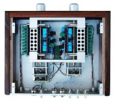
Looks good man Keep up the good soldering
") P.s Put new RCA wire in there, shielded stuff
P.s Put new RCA wire in there, shielded stuff P.s Put new RCA wire in there, shielded stuff
I also planned to mention that thing. Input and output wires all twisted together don't look to hygienic to me soundwise.
let's keep the twisted pairs and add shields.EUVL said:Mr. Carr's Masterpiece ?
> Shielding the wires is not needed.
Does no harm though, does it ?
Patrick
Where would you connect the shields? audio ground, input ground/return, PCB signal ground, Safety Earth?
- Status
- This old topic is closed. If you want to reopen this topic, contact a moderator using the "Report Post" button.
- Home
- Amplifiers
- Chip Amps
- Finishing up chipamp!