If there is no hum, just interferences pick up, more than likely it's the 300pf cap that is needed. It's been discussed here: http://www.diyaudio.com/forums/showthread.php?s=&threadid=55300&highlight=
Peter Daniel said:It is connected where bottom cover is installed.
Peter, to fit with any electrical code that I am aware of, the chassis, (safety), ground should be connected directly to the earth pin on the IEC connector with a wire of equal or larger thickness than used for the live and negative connections so it can support the full current load in the event of a fault. By all means use your earth lifting on the PSU and signal grounds, but not on the safety ground.
pinkmouse said:
Peter, to fit with any electrical code that I am aware of, the chassis, (safety), ground should be connected directly to the earth pin on the IEC connector with a wire of equal or larger thickness than used for the live and negative connections so it can support the full current load in the event of a fault. By all means use your earth lifting on the PSU and signal grounds, but not on the safety ground.
Pinkmouse, I can't really follow what you are trying to say here. Are you suggesting that I do not comply with "any electrical code that you are aware of"?
Peter Daniel said:Pinkmouse, I can't really follow what you are trying to say here. Are you suggesting that I do not comply with "any electrical code that you are aware of"?
I'm afraid so, I just don't want you to get hit with a lawsuit if anything ever goes wrong.
pinkmouse said:
I'm afraid so, I just don't want you to get hit with a lawsuit if anything ever goes wrong.
So your saying that using a resistor between the safety ground and the chassis ground is not up to code?
pinkmouse said:The chassis/case ground must be directly connected to the earth pin on the power connector or cable. You can do whatever you want with the PSU and signal grounds.
Pinkmouse, you obviosly missed something reading what I wrote here. Why don't you read it again, with proper understanding this time.
And try to refrain from safety reamarks, when we are discussing completely different issues.
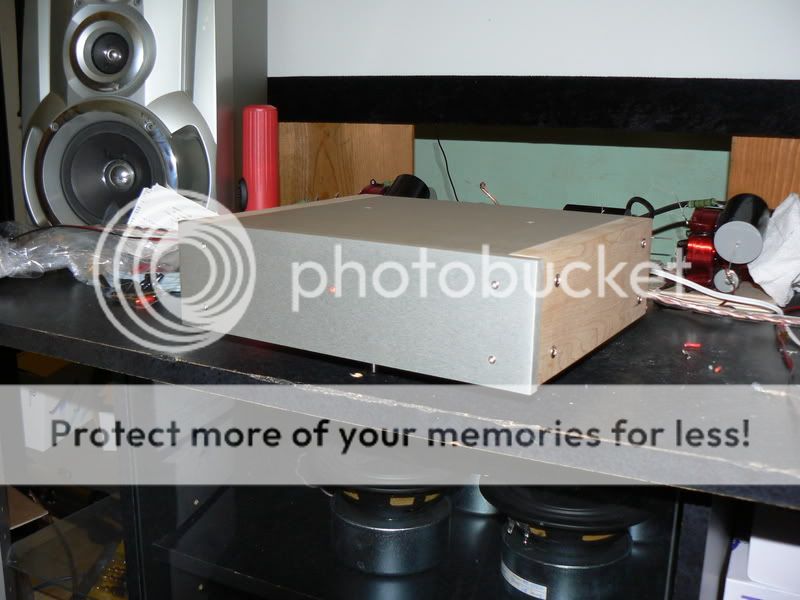
You saw the picture, but the picture didn't show complete chassis and didn't show complete product. Too bored playing moderator?
Dougie085 said:
So your saying that using a resistor between the safety ground and the chassis ground is not up to code?
The resistor is not between safety ground and chassis ground: it is between AC connector Earth pin and PCB ground.
The chassis is connected directly to Earth pin by a separate wire which couldn't be shown in a picture beacause bottom cover was not installed yet.
But why do I need to explain it to a moderator?
Peter, I didn't mean to offend, I was trying to be helpful, both to you and to anyone that might copy that design.
If you don't care about safety that's fine, but I do, and I would point out these things whether I was a moderator or not, and will continue to do so.
edit: As you saw from Dougie's post, it is very easy to misinterpret a picture and assume something you've seen is the right way to do things when it is not the complete article.
pinkmouse said:edit: As you saw from Dougie's post, it is very easy to misinterpret a picture and assume something you've seen is the right way to do things when it is not the complete article.
Listen, it is fine to be sensitive on safety issues, especially when you are a moderator, but this also brings responsibility of having clear judgement before passing an opinion or advice.
For that reason, you simply cannot judge a project that is not shown complete, which obviosly was the case here. So your eager reamarks where out of place, and simply annoying: we were not discussing safety ground connection, but power ground connections and that what the picture represented. If I want to discuss safety ground issues, I will post a different picture.
I don't mind if you remove those particular bits, that don't bring any useful input.
Hi Peter,
Excuse me for interjecting here, even though I'm a "moderator" as well. Moderators are members first, we just do extra work. But then again, you know that don't you? Try and drop that issue entirely as it had zero bearing on Al's remarks. Al being a moderator is an off topic issue.
From reading the preceding posts, I can see where Al was trying to clear up a little confusion. You are dealing with the grounding in an electrical device. The confusion was that it was thought (briefly) that the safety chassis connection was interrupted with a small resistor. That, as you well know, does not comply with Canadian Electrical code.
All you had to do was clarify the ground connections. There was need to take this on topic issue and create an argument. Al was really acting as a normal member, as am I. His comments were relevant to that issue.
-Chris
Well I messed with the grounding and now when I don't have anything connected to the inputs I don't hear the radio station just a low level hum thats hard to hear. But when I connect RCA's I hear the radio station. Tomorrow I'm going to grab some caps. As far as the hum I'm not sure. Guess I'll see if its still there after I put the caps in place.
The chassis is connected directly to Earth pin by a separate wire which couldn't be shown in a picture because bottom cover was not installed yet.
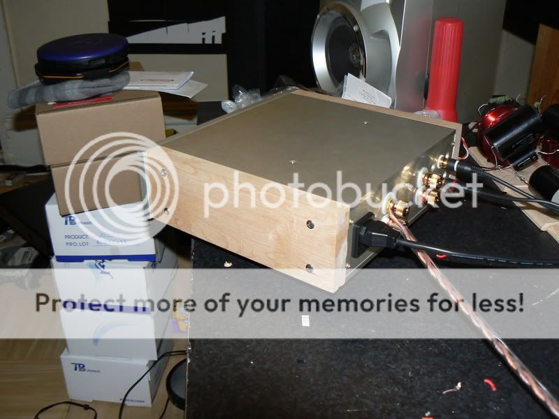
Peter, what may be causing some of us a bit of concern (or confusion) is that the ground tab of that IEC socket has the resistor soldered to it in such a way that the only way to attach another wire to it (the one you say is connected to the baseplate), is to solder it in position (you can't slide a receptacle on that ground tab with the resistor soldered there). The ground connection should be a mechanical connection not soldered.
I don't think anybody is having a go at you, but as you can see clearly from the posts, many newbies are constructing GCs still, and we have a duty to clear up any potential misunderstandings that may arise from anything said, or shown by, other contributors, more so when it comes to safety.
")
That hits it on the head.Nuuk said:
Peter, what may be causing some of us a bit of concern (or confusion) is that the ground tab of that IEC socket has the resistor soldered to it in such a way that the only way to attach another wire to it (the one you say is connected to the baseplate), is to solder it in position (you can't slide a receptacle on that ground tab with the resistor soldered there). The ground connection should be a mechanical connection not soldered.
I don't think anybody is having a go at you, but as you can see clearly from the posts, many newbies are constructing GCs still, and we have a duty to clear up any potential misunderstandings that may arise from anything said, or shown by, other contributors, more so when it comes to safety.
Safety FIRST, then try and sort the audio side.
The chassis pic without the safety earth fitted should at least have had a note pointing out the missing safety earth, but far better would be to show correct and safe construction, than that misleading and potentially dangerous pic.

Nuuk said:
Peter, what may be causing some of us a bit of concern (or confusion) is that the ground tab of that IEC socket has the resistor soldered to it in such a way that the only way to attach another wire to it (the one you say is connected to the baseplate), is to solder it in position (you can't slide a receptacle on that ground tab with the resistor soldered there). The ground connection should be a mechanical connection not soldered.
I don't think anybody is having a go at you, but as you can see clearly from the posts, many newbies are constructing GCs still, and we have a duty to clear up any potential misunderstandings that may arise from anything said, or shown by, other contributors, more so when it comes to safety.
As long as that duty is conducted in a polite manner, it won't bother anybody, but I will not tolerate people shouting is such way:
WHERE IS THE SAFETY EARTH?
Whouldn't it be much more appropriate to simply ask: "how do you plan to connect safety Earth?"
As to the IEC socket, I'm using solder tab type, so soldering is the only option: http://dkc3.digikey.com/PDF/C073/P1397.pdf
Each of my posts carries a link to a website, so when in doubt you can see there how things are done: http://audiosector.com/chassis_integrated.shtml (most recent amps have the safety Earth connected to a bottom plate though).
As to the IEC socket, I'm using solder tab type, so soldering is the only option: http://dkc3.digikey.com/PDF/C073/P1397.pdf
Interesting! I'm no expert on the regulations but I have always been told that the earth/ground connection has to be mechanical, ie crimped, and not soldered.
And I also thought that RoHS applied world-wide so I wonder if those IEC inlets at Digikey are old stock! Be interesting to get some confirmation on this subject!
- Status
- This old topic is closed. If you want to reopen this topic, contact a moderator using the "Report Post" button.
- Home
- Amplifiers
- Chip Amps
- Finishing up chipamp!