
 It was not working.!!!
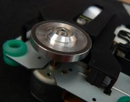
audio1st said:I have found a couple of different clamps recycled from other units.
The first is from a TEAC computer drive, which I have fitted to a motor with a 22mm shaft .
Have you run with one of these clamps yet, and if so what if any improvement have you noted? I'm thinking of doing the same thing, I was very disappointed with the clamp/puck assemblies I bought - it was a good effort but more difficult to achieve the required results than I imagined.
I'm running an RCEZ32 based version for which spare parts are almost non existent so I am hesitant to run the risk of wrecking a motor doing these experiments.. I'm going to get some spare parts soon from overseas.
Ok. I'm almost ready to admit defeat. But I can't help thinking that I've missed some basic step to getting this transport to work. Or, perhaps, I've somehow mangled both 31 transports in the same fashion. That seems kind of unlikely.
Still no music. Even from a stock transport that has only the R4 inductor removed and external 8v supply added. Everything on both transports seem to be working. Led (including light), TOC, laser motion, platform spin. Just no music. I do have the resistive network on the SPDIF output, 380/91.
Maybe I should hook the stock transport back to the original boards and PSU and see if it still plays in the boombox?
I'm not real experienced with digital audio equipment so I have quickly run out of ideas. I don't have access to a digital analyzer so I can't really see what SPDIF is doing. Is it possible that some DACs and transports just will not work together?
Hi audio1st,
Yes, I have double checked the DOUT connections. Nearest the TOC connector is ground, then 5v, then DOUT.
However, and this really raises my eyebrows, your posting of the drop across the resistor network that you see is much greater than what I believe I'm seeing. I'm seeing ~2vpp after the network. I'll double-check this again when I get home this afternoon. I even went to the trouble of making a 75ohm load with a resistor and female rca connector. I placed this on the end of the 6' coax so that I could measure both my 31 transport output and the digital output of the Marantz I'm using now. They appeared to be close, with the Marantz perhaps a bit more.
Anyway, thanks for mentioning this. I'll recheck the signal again.
Edit:
Hi John,
I have just finished assembling a Hagerman Chime kit and used my old Marantz 63SE as a transport to make sure the Chime was working. And it does, beautifully, with the Chime. Jim Hagerman designed this kit with a led for indicating SPDIF receiver ok (green light) and another led to indicate PLL reclocking is ok. When I try to play with the 31 transport I get a green light on the SPDIF receiver but not on the PLL reclock, and no music.
It does seem to point back to the SPDIF signal. I'll check with Hagerman but I bet that SPDIF led only indicates that a signal is present. So if it is overloading the circuit, that may drown out the information.
I'm wondering what the pull in range of the vcxo in the clock regenerator circuit is on the chime dac .. (You might want to ask Jim this question.) Are you using the recommended crystal or the original resonator?
And unloaded your digital out should be just over 1Vpp and loaded around 500mVpp based on my experience with those values. (I was one of the ones who made the recommendation for those values based on the spdif standard requirements.)
If you are not too far away you are welcome to come down sometime and I will check out your transports and see if I can find any issues. (I sent a pm a couple of hours ago to this effect.)
HI Kevin,
I just saw your email. Thanks for the offer! I'm just north of Salem, N.H. so driving down your way would certainly be a possibility. Hopefully, we can figure this out online. But if not I'll send you a note.
I have sent some questions off to Jim regarding the clock issue.
I also see from a post of mine a few days ago that I reported seeing 4vpp at SPDIF. Based on this and that you guys are telling me this should be a .5vpp signal I would say I really need to concentrate on this output. It is sure sounding like I'm saturating. First, I need to get my facts straight on what this amplitude really is.
The stock transport is still using the original oscillator. I have a second transport that I have done all of Peter's recommended mods to, so it has the Citizen crystal. I suppose the only common things between the two transports is the outboard psu and this SPDIF output network. Both transports are in the same situation. That is, everything seems to work but the music (PLL).
Hiii Peter
Maybe this picture give Peter Daniel a New Idea for Us
God Bless You
Looks day by day this project gone more crazy, lets continue
Congratz
Regards, Jeffry
Peter Daniel said:Maybe that picture gives you some ideas
An externally hosted image should be here but it was not working when we last tested it.
Maybe this picture give Peter Daniel a New Idea for Us
God Bless You
Looks day by day this project gone more crazy, lets continue
Congratz
Regards, Jeffry
Here is what I measured last night for DOUT. Without grounding the probe I see a 4.8Vpp sine wave. I'm not sure what this is.
When I ground the probe and measure DOUT I get a .5v signal before the voltage divider. I believe this does match the spec sheet on the 78601. Page 4 states that the low-level output at DOUT is .1 Vdd, which gives the .5v. This drops to about 80mV after the voltage divider.
I'm not sure how to relate what I'm seeing to what others are reporting.
Dan_ed said:Here is what I measured last night for DOUT. Without grounding the probe I see a 4.8Vpp sine wave. I'm not sure what this is.
When I ground the probe and measure DOUT I get a .5v signal before the voltage divider. I believe this does match the spec sheet on the 78601. Page 4 states that the low-level output at DOUT is .1 Vdd, which gives the .5v. This drops to about 80mV after the voltage divider.
I'm not sure how to relate what I'm seeing to what others are reporting.
I think you are misinterpreting the specification and the levels you are citing are way off the mark. I wonder if your scope has enough bandwidth to handle the spdif signal. You would want a minimum of a 20MHz scope to avoid serious amplitude and response errors.
The voltage at the DO output unloaded is about 0.5V less than Vdd when high - so about 4.5V typical, and about 0.1V greater than Vss (ground).. So normally you would expect to see something like 4.4Vpp on the DO without the divider connected, current capability is high enough that the output voltage will not drop significantly when you attach the divider. The output of the divider should be about 800mVpp - 1Vpp and with a 75 ohm termination it will be half this.
Most spdif receivers will not work properly at anything below about 200mVpp and this is very marginal.
You need to take another look at what you are doing or have someone else take a look..
It is a Tek 465 100Mhz scope and I'm using a 10x probe. I haven't owned this scope/probe very long so I'm still getting to know and trust it. I should probably get a new probe even thought this one seems to work.
However, being that neither transport is working for me it seems that perhaps these measurements could be telling me that something upstream isn't right. Or, I have somehow fried them both in the same way.
You are right. It is time get another set of eyes on this.
Thanks for the explanation on the specs.
Yes. I did try without the voltage divider. Same results.
The network is: 390 ohm in series, 91 ohm to ground, RCA jack
Dan_ed said:It is a Tek 465 100Mhz scope and I'm using a 10x probe. I haven't owned this scope/probe very long so I'm still getting to know and trust it. I should probably get a new probe even thought this one seems to work.
However, being that neither transport is working for me it seems that perhaps these measurements could be telling me that something upstream isn't right. Or, I have somehow fried them both in the same way.
You are right. It is time get another set of eyes on this.
Thanks for the explanation on the specs.
Yes. I did try without the voltage divider. Same results.
The network is: 390 ohm in series, 91 ohm to ground, RCA jack
I'll bet your 10X probe is the culprit here, either you are not compensating for the fact that it is 10X (some probes are compatible with the gain scaling features on some scopes and others are not) or the probe is bad.
Good call, kevinkr! I borrowed a 100x probe from the hardware lab at work and I think I'm on to this. I think.
With a good probe last night I measured .6Vpp under load from the Marantz. The shig'er is putting out .4Vpp under load. So I changed the voltage divider with some resistors I have on hand. Now the Shig is putting out just under .6V but still no music.
The signal from the Shig is actually a better looking wave. I'll try to get some pictures tonight.
Edit:
I just saw a note from Jim saying that the signal level is fine and that I perhaps should look at timing. The signal needs to be within 100ppm.
Dan_ed said:Good call, kevinkr! I borrowed a 100x probe from the hardware lab at work and I think I'm on to this. I think.
With a good probe last night I measured .6Vpp under load from the Marantz. The shig'er is putting out .4Vpp under load. So I changed the voltage divider with some resistors I have on hand. Now the Shig is putting out just under .6V but still no music.
The signal from the Shig is actually a better looking wave. I'll try to get some pictures tonight.
Edit:
I just saw a note from Jim saying that the signal level is fine and that I perhaps should look at timing. The signal needs to be within 100ppm.
Hi Dan,
I suspect that if you are using the stock resonator in your shigaclone this could be part of the problem. Choose a crystal with a tolerance of 25ppm or better. (Or use the one Peter recommends.) I know that the lock range on the hagdac is relatively narrow, although I never had problems with this issue. It is designed for 44.1kHz clock rate only..
Just to do every once in a while a reality check...Anton took the time to modify a Wadia 23 (on request) with a Trichord 4 (same as the PitBull) and a ALWSR reg (same as the PitBull) and made a proper supply...
Besides the fact that this Wadia 23 "oldtimer" immediately made lovely music and ranked itself between the better transports it was simply no match for the PiTBull ...no hype just a more analog transport with more resolution better bass etc etc...
For comparison I played Bach Lute Music with J. Lindberg
(my favorite Lutist for Bach...and I got a lot of lutists recordings)
He is present in your living and the complete lute-timbre is captured...
Attachments

- Home
- Source & Line
- Digital Source
- Finally, an affordable CD Transport: the Shigaclone story