sparkle said:oh man !!!
so many questions....
has anybody any idea how to buffer the signal for the digital out....??!
maybe something using 74HC74....?????
Why you would buffer that anyway?
I made some meausurements with osciloscope. Signal is pretty ok on both ends.
I am just preparing some aditional tests with diferent connections. I beleive that will able to show results of measurements after finish.
Answer on your question is maybe here:
Digilampizator
and
FETishizator
Man has huge imagination!!!!

sparkle said:hmmm.... digilampizator seem not to be optimized at the output ... not spdif output impedance.....
it is questionable if this will work that good.....
can somebody tell me if somebody tried that mod anywhere (digi-lampizator)....????
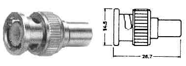
There is no need for 75 Ohms exactly. Digital out don't care if it is 50, 75 or 93 Ohms or any other. So you can adjust impendance to media and connectors you have. E.g. you can use BNC 50 Ohms RG 58 coax.
The problem can arise at external DAC input if this can't be changed. So you need to stay with 75 Ohms.
valo said:
I did buy a clone of the wadia att board on ebay but iam not 100% sure that my card has the same chip as youre card has.
I did use 1% caps and 0.1% precision resistors on the boardn just becaus i did have them here
If iam not wrong the chip on youre ATT card shuld be maked DS26LS31
Hi Valo,
The outputboard is from Wadia 22/23.
On this board the AM26LS31CN chip is fitted followed by a CTS ODL 50 series 2 for ST-optical.
The AM26LS31 is pin compatible with DS26LS31.
Anton.
a question - has anyone tried Elso Kwak clock in the Shigaclone?? how is it working t
Kwak clock 7 sounds fantastic after simple resonator elimination in my case.(AC psu with chokes for clock , Pb batteries on transport).
Thanks Peter,Okapi,Erik...........and everybody.
Kwak clock 7 sounds fantastic after simple resonator elimination in my case.(AC psu with chokes for clock , Pb batteries on transport).
Thanks Peter,Okapi,Erik...........and everybody.
sparkle said:oh man !!!
so many questions....
has anybody any idea how to buffer the signal for the digital out....??!
maybe something using 74HC74....?????
There's no need to do that, the Dout signal is capable of driving the load. But if you'd still want to buffer it, in the attachment you will find one way of doing it. U1 is a 74HCT04, C1..C3 can also be replaced with a single 150p cap.
I simply use R1 and R2 directly on Dout and GND.
Attachments
For your interest, here's the output circuit in CEC TL0:
An externally hosted image should be here but it was not working when we last tested it.
dzuvela said:
There is no need for 75 Ohms exactly. Digital out don't care if it is 50, 75 or 93 Ohms or any other. So you can adjust impendance to media and connectors you have. E.g. you can use BNC 50 Ohms RG 58 coax.
The problem can arise at external DAC input if this can't be changed. So you need to stay with 75 Ohms.
Yes and no. If the complete chain is 50, 75 or 93 ohms, you're correct, but mismatching in- and outputs will lead to reflections. Altering a 75 ohm input of a DAC would definitely not be my first choice as the circuitry behind the input may also need to be modified.
Real life is never perfect, so achieving exactly 75 ohms is unlikely, but 50 ohms will be a heavier drain on Dout than a 50% higher (i.e. 75 ohms) impedance.
IMO, the Dout signal in combination with the layout of Dout, GND and Vcc on the pcb has "Toslink" written all over it. You could just solder in a Toslink transmitter (TOTX177) and it should work. It's not designed for coaxial S/PDIF. Adapting it to drive a coax at S/PDIF levels (500 mVpp) and 75 ohms impedance is (just) possible, but 50 ohms might be too much for the Sanyo IC without some buffering. Buffering equates to extra components which I'd rather avoid.
Safest and simplest is to stick with 75 ohms.
Peter Daniel said:For your interest, here's the output circuit in CEC TL0:
Thanx, this is useful info. As I have a DAC which also has an AES/EBU input, I was thinking of converting the output of the Shigaclone to balanced mode...
guys thanks for the informations.... ... much appreciated....
another thing..... i have sometimes a problem that my Shiga makes a click or somethng like that (like the cd is scratched but it is not and it does that with originals too), while playing.... i did not mess with the clock just yet... only those capacitors and that inductor on the pcb of the transport.... can anyone suggest what it might be........
... any ideas...
thnx
jitter said:
Yes and no. If the complete chain is 50, 75 or 93 ohms, you're correct, but mismatching in- and outputs will lead to reflections. Altering a 75 ohm input of a DAC would definitely not be my first choice as the circuitry behind the input may also need to be modified.
This is what I mean. Whole chain the same.
jitter said:
Real life is never perfect, so achieving exactly 75 ohms is unlikely, but 50 ohms will be a heavier drain on Dout than a 50% higher (i.e. 75 ohms) impedance.
IMO, the Dout signal in combination with the layout of Dout, GND and Vcc on the pcb has "Toslink" written all over it. You could just solder in a Toslink transmitter (TOTX177) and it should work. It's not designed for coaxial S/PDIF. Adapting it to drive a coax at S/PDIF levels (500 mVpp) and 75 ohms impedance is (just) possible, but 50 ohms might be too much for the Sanyo IC without some buffering. Buffering equates to extra components which I'd rather avoid.
Safest and simplest is to stick with 75 ohms.
Yes I can agree, 50 Ohm may be to low for Dout. According to the datasheet, Dout works at 12 mA and voltage is beetween 0,1 and 0,9 of Vdd (5V in this case) depends of Hi Lo signal state. There is no data about maximal current or minimal impendance as I've seen.
It's happenned that I have rests from company old network coax ethernet and Arcnet which are 50 and 93 Ohms respectively. This includes BNC connectors, "T" elements, cables and terminators.
Temporary I will adapt ext.DAC input from 75 Ohms to "no impendance" . At transport side, Dout is not terminated yet. Connections on both ends will be "T" ends with terminating resistors of BNC type. This is kind of BUS connection.
I am just curious what I can get here. Even more, it is possible to change cable types and resistors and see if any difference. (93, 75 or even 50 Ohms)
IMO optical interface is one which should be the best. Only thing I am worried about it is life cycle of Tx diode. At the TOS cataloges, this fact is always clearly marked.
Although don't understand why this is possible since I have ST type of optics all around working for more then 10 years now.
So, according to that TOS link is not serious option.
Attachments
My shiga recently developed a habit of clicks and stutters every now and then, on a variety of CDs. A spray of some silicone spray (ie Ultraglide) carefully applied to the rails (and rails only) has sorted the issue out.
Its a dry spray so hopefully shouldn't attract any dust.
Fran
Its a dry spray so hopefully shouldn't attract any dust.
Fran
yes i have tried the digilampizator and it works brilliantly.
Very simple circuit and the valves are very cheap and easy to find.
I just source the spdif output pin direct from IC then run it through the digilamipzator.
The change in sound is very reminiscent of changing a digital output IC opamp into a fully discrete one. More detailed more transparent and more immediate sounding.
Build no. 2 is going well, all the mods are done to the mechanism now and the casework is almost finished.
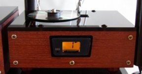
This one is simpler in many ways than my previous one. Its isn;t suspended right now - although I may add that later. The transformer is in a separate box with rectification/regulation in the mechanism box. This mech came from a EZ-51 and the smaller display board is much easier to house. In this one, the board will just be mounted behind a new fascia and I have some buttons made that will just attach to the buttons on the PCB. Other than that its pretty standard....
And the baseplate it will sit on:
That baseplate is some kind of ceramic compostie material. Its really really heavy and I hope my wet tile saw wil cut it to size. I have 2 blocks of it and I may end up using the other one yet. Its too big right now so I need to cut it back to fit the shelf.
Fran
This one is simpler in many ways than my previous one. Its isn;t suspended right now - although I may add that later. The transformer is in a separate box with rectification/regulation in the mechanism box. This mech came from a EZ-51 and the smaller display board is much easier to house. In this one, the board will just be mounted behind a new fascia and I have some buttons made that will just attach to the buttons on the PCB. Other than that its pretty standard....
An externally hosted image should be here but it was not working when we last tested it.
An externally hosted image should be here but it was not working when we last tested it.
And the baseplate it will sit on:
An externally hosted image should be here but it was not working when we last tested it.
That baseplate is some kind of ceramic compostie material. Its really really heavy and I hope my wet tile saw wil cut it to size. I have 2 blocks of it and I may end up using the other one yet. Its too big right now so I need to cut it back to fit the shelf.
Fran
sparkle said:guys thanks for the informations.... ... much appreciated....
another thing..... i have sometimes a problem that my Shiga makes a click or somethng like that (like the cd is scratched but it is not and it does that with originals too), while playing.... i did not mess with the clock just yet... only those capacitors and that inductor on the pcb of the transport.... can anyone suggest what it might be........
... any ideas...
thnx
woodturner-fran said:My shiga recently developed a habit of clicks and stutters every now and then, on a variety of CDs. A spray of some silicone spray (ie Ultraglide) carefully applied to the rails (and rails only) has sorted the issue out.
Its a dry spray so hopefully shouldn't attract any dust.
Fran
I'm thinking there might be quite some variation in quality between the different transports because some report these kinds of problems whereas most do not.
Sadly mine also has issues with less than perfect CD's. Light scratches are no problem but anything more serious leads to clicks and skipping. I also find the servos very noisy, esp. on some CD-R's. It's as if it's struggling to play them, so I'm expecting it to click and skip on them if the transport has had some more wear. This, BTW, is something I've on noticed on other boom-boxes in the past as well.
I don't know if the system of error correction in CD-players can be implemented in more than one quality. By that I mean if a manufacturer can actually choose to have some (cheap) transports do error correction in a less sophisticated way than a more expensive transport. Or is it that the laser mechanism has been constructed of such quality (down to a price) that it's barely able to function correctly when new?
Whatever the case, on good CD(-R)'s, it sounds very well, and I've yet to start the upgrading (other than a PSU and the removal of some components, I haven't done anything else yet).
I believe that I read somewhere that there is minimal error correction with the shiga mechanism. So if there is a flaw in the disc, you get clicks and pops. My mech is fairly quiet though... you would hear it in between tracks and at the end/start of a disc, but you wouldn't hear it during play. Maybe all CDPs are like that though and its just because the mechs are exposed in a lot of the builds here that its more noticeable.
I also remember reading that the less error correction there is the better the mech sounds. So that may be part of the magic of this thing.
Fran
I also remember reading that the less error correction there is the better the mech sounds. So that may be part of the magic of this thing.
Fran
woodturner-fran said:Maybe all CDPs are like that though and its just because the mechs are exposed in a lot of the builds here that its more noticeable.
I can tell you for a fact that that's not the case. I have a Nakamichi CDP with a metal Sony mechanism (with KSS150A laser) and a Primare with a Philips mechanism (CDM12.4). I heard both several times with the lid off. The Nak is pretty noisy and makes a lot of hissing noise (not unlike the Shigaclone). The Primare is whisper quiet.
This may not be the "fault" of the mechanism alone. The Nak seems to have a standard Sony implementation, but I believe that Primare customized the controlling software to lower servo activity compared to the standard Philips implementation. I once heard a similar mechanism in a Marantz and it was much louder. The resulting increase in sensitivity for vibration has been dealt with by weight: the housing of the Primare is constructed fully of 2 mm thick steel. The error correction is not as good as the Nak, but far better than the Shiga. This CDP is very musical.
When I put the Shigaclone's mech on a piece of chipboard, the noise got worse (the board acts as mechanical amplifier). I'm not surprised most used hard suspension and a lot of weight to get these vibrations under control. Weight will not prevent vibrations from ocurring, but it will lower their frequency and probably also amplitude. It will be one of my next steps in modding the Shiga.
I also remember reading that the less error correction there is the better the mech sounds. So that may be part of the magic of this thing.
IMHO this might be true in the case where error correction can no longer reconstruct the data 100%. Once the correction needs to fill in blanks based on guess rather than fact, it will no longer be true to the original data.
- Home
- Source & Line
- Digital Source
- Finally, an affordable CD Transport: the Shigaclone story