valo said:Eric what chip is mounted on youre AT&T card is it the DS26LS31? and do you have a close up picture of the card
I will ask Anton about the chip since I have not the slightest idea....
I have posted a few close ups if I recall correctly...
The best thing I reckon is to ask on e-bay who is willing to sell his Wadia ATT board...especially with new clock-rca-users you stand a pretty good chance they do not use the board....

@Hotiron...about my invested amount of time I can only quote your signature.....if you give up easily do not start...
Erik van Voorst said:
I will ask Anton about the chip since I have not the slightest idea....
I have posted a few close ups if I recall correctly...
The best thing I reckon is to ask on e-bay who is willing to sell his Wadia ATT board...especially with new clock-rca-users you stand a pretty good chance they do not use the board....
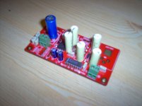
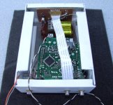
I did buy a clone of the wadia att board on ebay but iam not 100% sure that my card has the same chip as youre card has.
I did use 1% caps and 0.1% precision resistors on the boardn just becaus i did have them here
If iam not wrong the chip on youre ATT card shuld be maked DS26LS31
Attachments
sparkle said:dzuvela.... you were busy.....
nice looking....!
sound??
satisfied??
thank you sparkle
Yes I am satisfied. Waiting for new digital and TOS cables. then I will do some more experiments with those two interfaces.
Analog output level is significantly lower. Couple of tubes would help here a lot.
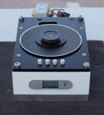
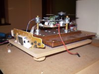
dzuvela said:bottom look.
Display panel with remote sensor and backlight diode completely redisigned. Only ribbon conector with piece of original panel board cut mounted on new board.
Power suply board is also new.
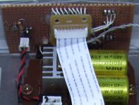
If that Rifa PEG caps i see?
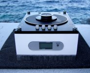
sparkle said:at my place, the "thing" is currently looking like this.....
BG cap's on the pcb added, new power supply burned in, moving forward a bit with the mechanic stuff....
I am glad that your BGs are finally burned on. I am using used RIFA. So they are definetly burned
Need to solve door switch mechanic yet. There is REED contact now driven by litle magnet.
Base plate is cut, 15 mm Al plate. Yet need to be driled for bolts and spikes.
Generally, I can say that whole thing is assembled from vasted materials and components.
Recycled parts, but sounding great.
Attachments
dzuvela said:
thank you sparkle
Yes I am satisfied. Waiting for new digital and TOS cables. then I will do some more experiments with those two interfaces.
Analog output level is significantly lower. Couple of tubes would help here a lot.
the analogue outuput level is lower but when it is working for about half an hour or a bit more, than it start to be a bit louder.... still not loud like normal but it is o.k. - we all are used to much higher levels of signal entering in our amplifiers... not really necesary but ....
i guess maybe only some buffering will be nice... nothing more.....
....
sparkle said:
the analogue outuput level is lower but when it is working for about half an hour or a bit more, than it start to be a bit louder.... still not loud like normal but it is o.k. - we all are used to much higher levels of signal entering in our amplifiers... not really necesary but ....
i guess maybe only some buffering will be nice... nothing more.....
....
I agree.
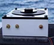
According to schematic and what I can see from board, outputs are taken directly from chip, passing through discrete filter.
In Boombox application this was OK since amplification was close.
Conecting to external component some buffer should be applied. First thing what came to my mind is some of Low noise dual OP which is posible to add in to drive housing.
anyway - this player like on that picture from this link http://www.diyaudio.com/forums/showthread.php?postid=1739608#post1739608 is playing right now like crazy ... i think that the only thing i will change is that mdf board - i will convert it to real wood block... beech wood to be exact..... it is heavy, sounds good and it is nice to work with....
i see that this thread is practically dead.... to bad...
still - some folks might look arround and i have another question....
has anyone tried this clock too.... it is nice since it is going on 8V but it is not completely the same like Kwak Clock 7... so it can be modified a bit to look like Kwak no.7 that is running on 8Vdc that i allready have on my Shiga psu....
the link is here....
http://home.quicknet.nl/qn/prive/ra...cknet.nl/qn/prive/ra.vdsteen/cd_clock_en.html
- Home
- Source & Line
- Digital Source
- Finally, an affordable CD Transport: the Shigaclone story