ok seems it works... hope moderator will aprove all parts simultanously.
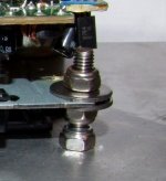
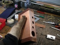
2. Hanging mechanism detail
As you can see from photo 4 bolts and 3 nuts per bolt are used. This give me option to fine adjust mechanism position against base plate.
All nuts and bolts are stainless steel, so no-magnetic influence.
2. Hanging mechanism detail
As you can see from photo 4 bolts and 3 nuts per bolt are used. This give me option to fine adjust mechanism position against base plate.
All nuts and bolts are stainless steel, so no-magnetic influence.
Attachments
dzuvela - here you can find some more informations about my shigaclone......
also some more pic's
http://www.accosijek.com/forum/index.php?topic=616.0
regards
also some more pic's
http://www.accosijek.com/forum/index.php?topic=616.0
regards
are the actions from page 2 from manual nesasary on http://tim.cheapo.cc/images/CD player mods.pdf
I don't want to brake main board
I don't want to brake main board
samoloko said:are the actions from page 2 from manual nesasary on http://tim.cheapo.cc/images/CD player mods.pdf
I don't want to brake main board
Well, not strictly if you don't mind what many would term fairly to extremely mediocre performance, and the spdif output connections are necessary. My RC-EZ32 based unit sounds quite mediocre until I did the comparable mods to it. (I would not have kept it with the stock level of performance which I found very uninvolving.) Most of the pitfalls encountered by others seem to have been making wrong connections to the board or display.
...
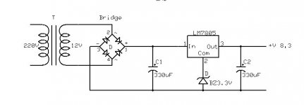
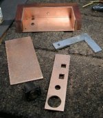
3. Power supply
Electrically this perfectly ok.
Original trafo, bridge, regulator 7805 plus zener diode 3.3V gives 8.3 V and it is working perfectly ok. I am in doubt about using bigger trafo. Seems no much reason for that. Existing trafo from JVC do not heat at all or very litle. Will check with osciloscope later.
I read about 47lab philosophy about not using big energy acumulators on any way. Here I used 2 RIFA 330uF each. Whole thing sound perfect. Well I am going give a try to bigger capacity in near future.
Attachments
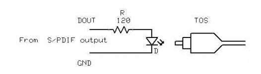
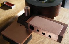
4. Signal line.
Here I made bit funny thing.
Red lighting diode from optical mouse and 120 Ohm resistor in serie directly to S/PDIF output as shown on schematic.
Against diode I put open end of optical kabel and lead it to external DAC optical input.
You wouldn't belive this work so great.
Look in real at the photo in next post.
Attachments

dzuvela said:
2. Hanging mechanism detail
As you can see from photo 4 bolts and 3 nuts per bolt are used.
Many of us, included me, have experienced a better sound with three or two (better) standoffs. You should try. I use two and have not any planarity issue.
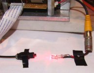
dzuvela said:Optical link in action
This is all so far. There will be more after the Christmass .
Does it WORK?
brgds said:
Does it WORK?
Sure it works.
I am thinking about to make adapter consisting of chinch connector on one side, diode and resistor in the midle and some rubber to fix TOS connector at other end. This way any coaxial output culd be used as optical source, without impedance issues. Disconecting it one can use coax again.
Funny isn't it?
The catch is that TOS link itself is very primitive in compare to professional optical links, for data transfer or in telephony e.g. Special fiber optics is used, laser diodes working in invisible range of light, and so on....
TOS is simple and primitive, piece of transparent plastic thread and red diode light. But working great at small distances.
m.massimo said:
Many of us, included me, have experienced a better sound with three or two (better) standoffs. You should try. I use two and have not any planarity issue.
I know that reports about 2 or 3 standoffs. I believe that I can tight mechanism plate precisely adjusting nuts at each corner avoid any bending of the the mechanism base.
Forgot to mention two more things.
Nuts are all selflocking. Ordinary stainless nuts can unscrew easy.
And...
The main axe of CD drive/motor is placed in the center of Al plate. This way I got mechanically symetrical position of the center of rotation what would result with overall better mechanical behavior.
Aditional balancing will be done by ading weight oposite to the rest of mechanism position.
( similar to the vehicle teers balancing )
Dumping elements will be placed in plane which is parallel and as close as possible to the plane of top plate. This way all vibrations must have its minimum. Will be more clear in couple of days when I can have photo or draft.
To achive all this, 4 bolts or stanfolds should be better solution. But of course nothing is easier then unscrew 1 to 2 nuts to check difference.
Finally, dumping material is important too. More about later.
brgds said:dzuvela,
have you compared sounding of your primitive toslinkwith coax?
Honestly haven't heard any difference. But also need to set up better listening equipment. I mean on headphones.
I was more in mechanical stuff this first period. Some measurement follows as well more accurate listening.
Regarding my funny TOS link. It just happened that I had no proper TOS adapter by hand, so made one my own. Of course this will be compared with more professional one.
dzuvela said:
Sure it works.
The catch is that TOS link itself is very primitive in compare to professional optical links, for data transfer or in telephony e.g. Special fiber optics is used, laser diodes working in invisible range of light, and so on....
TOS is simple and primitive, piece of transparent plastic thread and red diode light. But working great at small distances.
The AT&T output easily outperformed the coax, resulting in an overall better presentation with more body and more timbre.
Actually the same end results as the Coax/AT&T comparison on the Wadia transport...
Ofcourse most of the problem is that the dac has to accept AT&T
and in real life it is proven that the best things will not always become standard (not only in audio)......
Erik van Voorst said:
The AT&T output easily outperformed the coax, resulting in an overall better presentation with more body and more timbre.
Actually the same end results as the Coax/AT&T comparison on the Wadia transport...
Ofcourse most of the problem is that the dac has to accept AT&T
and in real life it is proven that the best things will not always become standard (not only in audio)......
Now I understand why you use separate psu and sup reg for: "AT&T (outputboard) has a psu (non polarized blackgates) and sup reg".
Could you advise more info on this output board, please?
I was lucky to be able to take it out of my Wadia Transport after it was decided that the PiTbull Transport was gonna be my future rig....
Since I will use the Wadia as a spare transport and with a Tent clock via cinch I can do without this complete AT&T board in the Wadia (ofcourse that At&T board also takes cinch toslink and AES).
You will have to google and find out were they sell AT&T stuff or ask a friend with a Wadia 22/23 if he is willing to sell the board of his old Wadia.....or maybe a broken down Wadia (which will be rare...)
I will tell you will have a hard time getting an AT & T cable....maybe you run the most easy into a Wadia AT&T cable since highend makes are few...
Today I completed the shielded box for it...
Attachments


Erik van Voorst said:Hello guys
Is there anybody out there who has a longer (display) ribbon than the standard ribbon supplied.
I am very willing to pay the expenses.
I know that it is possible to hardwire it but that is a lot of extra work and besides not easy to make it detachable.
I have been on the internet and also visited a lot of shops.
The problem is also the correct width between the wires so cutting a wider ribbon is not always the right solution.
I reckon a 30 cm will be perfect

- Home
- Source & Line
- Digital Source
- Finally, an affordable CD Transport: the Shigaclone story