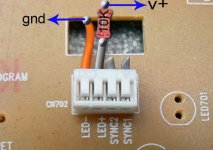
Badge said:I put a 10K ohm resistor in series off the DC output of the power supply. I never did see any back light so I checked voltage. I had 7.5 volts. I am assuming I destroyed the LED? How do I access the LED for replacement? Looks like the whole display needs to removed? So close yet so far.
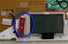
Just remove the triangular lid and desolder the LED from the back..
Attachments
Badge said:I put a 10K ohm resistor in series off the DC output of the power supply. I never did see any back light so I checked voltage. I had 7.5 volts. I am assuming I destroyed the LED? How do I access the LED for replacement? Looks like the whole display needs to removed? So close yet so far.
It isn't necessarily the case that you destroyed the LED, you must have connected it backwards though. (The led reverse breakdown voltage is certainly lower than 7V, but the current was limited and it might/might not have survived the experience.) Recheck the connections first, (no errors, missing ground?) reverse them if necessary and then if finally replace the LED if necessary.
valo said:
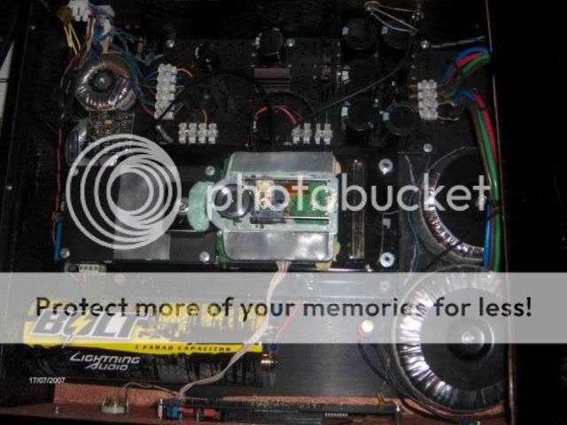
I got the idea from this cdplayer, and this one is not an DIY player .. looks like a mess in ther but nice on the outside
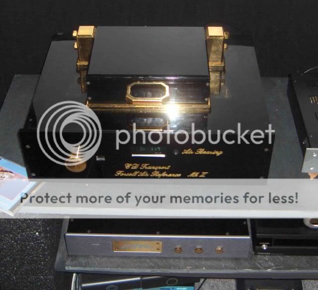
anyway iam saving my big caps for an nie amp
Hi Valo,
Don´t mind me asking you this question but why change or try to modify a ´VERY GOOD´ transport like the Forsell Air Reference

Anton.
Badge said:Thanks for the info on my LED. I did check it with a meter and get no forward resistance so I did fry it.
Consider it an opportunity to choose the color for the display that you desire. I really did not like the orange, but the blue looks really nice now. It is an easy replacement.
ccschua said:Is it possible just to purchase the LCD panel as replacement ?
i doubt you will find the LCD panel .....
maybe if somebidy that allready used the transport, has some panel that he does not need.....
otherwise, i doubt it....
ccschua said:Is it possible just to purchase the LCD panel as replacement ?
I would say no.
If you disconnect the ribbon is it still showing "38"?
Have you removed Q702? (you must if damaged).
Sorry to say you have most likely damaged a chip on the transport board.

The display should not prevent the transport from working.
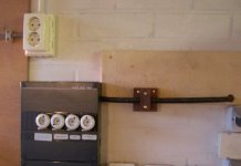
think i did kill my transport today .. i did mount the regulator to the frame but i did forget to isolate if from the frame .. my transport canot find tracks on the cd anymore, the display onely show 00 now..
iam going to order an new jvc rc51 now..
iam thankful for anyhelp that can bring my board alive again
iam going to order an new jvc rc51 now..
iam thankful for anyhelp that can bring my board alive again
valo said:think i did kill my transport today .. i did mount the regulator to the frame but i did forget to isolate if from the frame .. my transport canot find tracks on the cd anymore, the display onely show 00 now..
iam going to order an new jvc rc51 now..
iam thankful for anyhelp that can bring my board alive again
Provided that you used an LM7808 regulator or one of its many variants the tab is at ground potential - more likely that you made some other error that resulted in an over-voltage to your board. (Like swapping the input and output pins on the regulator..) If you are sure you did not do this then you might want to check for other issues - I had the same problem when I did not have the mechanism ribbon fully seated.
Here is a link to the spec sheet for the Fairchild version of the part which shows very clearly what each pin is..
http://www.fairchildsemi.com/ds/LM/LM7808.pdf
kevinkr said:
Provided that you used an LM7808 regulator or one of its many variants the tab is at ground potential - more likely that you made some other error that resulted in an over-voltage to your board. (Like swapping the input and output pins on the regulator..) If you are sure you did not do this then you might want to check for other issues - I had the same problem when I did not have the mechanism ribbon fully seated.
Here is a link to the spec sheet for the Fairchild version of the part which shows very clearly what each pin is..
http://www.fairchildsemi.com/ds/LM/LM7808.pdf
No , i have the rigth regulator an lm7808 and it gives me 8v, and everything did work just fine before i mounted the regulator on the frame..
valo said:.. my transport canot find tracks on the cd anymore, the display onely show 00 now...
Hi valo,
I used to have the same problem...found a few wary tiny cracks in display PSB board as well as main board. Use a magnifying glass and light bending to see offending PCB traces, solder them and you'll be back in business.
aparatusonitus said:
Hi valo,
I used to have the same problem...found a few wary tiny cracks in display PSB board as well as main board. Use a magnifying glass and light bending to see offending PCB traces, solder them and you'll be back in business.
My display board is heavy modyfyed, just the connector left of it , but it did work just fine before i mounted the ergulator to the copper frame whit out isolating the regulator..
I did order a new JVC today so i shuld be back in business werry soon
valo said:
I got the idea from this cdplayer, and this one is not an DIY player .. looks like a mess in ther but nice on the outside
[....]
anyway iam saving my big caps for an nie amp
Sorry for the offtopic on my part....
Valo your first picture has got nothing to do with Forsell's electronic layout and his CDM9 pro 'airdamped' mechanism

So I think this contrapsion must be a DIY
Anton.
scrutinizer said:
Sorry for the offtopic on my part....
Valo your first picture has got nothing to do with Forsell's electronic layout and his CDM9 pro 'airdamped' mechanism
So I think this contrapsion must be a DIY
Anton.
Thats rigth Anton, the first picture i did post here is my DIY cdplayer.. the modyfyed Forsell is not mine .. I onely wanted to show you guys the 1F cap that its inside it ..
- Home
- Source & Line
- Digital Source
- Finally, an affordable CD Transport: the Shigaclone story