DaveM
On the right lower edge of the PCB, looking from the top with the spindle motor in the front, you will see DOUT and GND. That is where I got the digital output. DOUT, Resistor, 1 leg of transformer. The other leg of transformer to GND as per attachment I sent. I think there was a picture in the document Peter provided at the beginning of this thread. If you need more help I will try to take a picture.
Hope this helps
JimS
After I install the external clock from this one.
http://www.audio-gd.com/enweb/pro/diy/JZ-1.htm
All I can say is that is the final mod that I have done. I am so thrilled with the sound.
http://www.audio-gd.com/enweb/pro/diy/JZ-1.htm
All I can say is that is the final mod that I have done. I am so thrilled with the sound.
Havoc08 said:So I have all but given up on finding a EZ31, but there seem to be quite a few of EZ51. I have downloadet the PDF on the mods to be made, but before purchasing I would like to confirm that the EZ51 can be used as a replacement for the EZ31.
Thank you in advance")
...sugestion....read whole thread.
Yes EZ51 boards are exactly like EZ 31 ( and probably easier to source still )...except display...in some details.
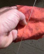
Today I made the siver cable connections from the power supply box to the actual transport...
I am a strong believer in NFO (natural fiber only) and value the reports on Micro Discharge (google)..
Also one of my home-made cables configured that way outperformed the existing ones with a considerable margin.
So I use.....0.8 mm Silver..Ricepaper..Silk..Cotton .
This will be the japanese way to go....Zen Patience is a must here ......it takes me 4 hours for 2 times 0.75 cm...........but what the hell...the weather is awfull overhere anyway.....................
Turn after turn...
Attachments
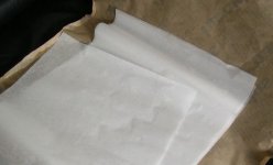
Since there is very little to be found on the internet regarding this technique I hope the ones who already know forgive me going into detail.
I cut very small but long pieces of ricepaper.
Two will take care of 75 cm single core cable...
I do the same with the silk cloth...
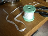
The spool contains the silver I bought quite a lot so I can go crazy...
I cut very small but long pieces of ricepaper.
Two will take care of 75 cm single core cable...
I do the same with the silk cloth...
The spool contains the silver I bought quite a lot so I can go crazy...
Attachments
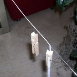
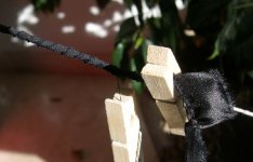
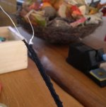
Each new winding goes exactly in the middle of the previous layer this way you get a very even end result which is crucial for its performance....
Over the entire length I tighten everything with a cotton thread.....I follow again exactly every turn...
Over the entire length I tighten everything with a cotton thread.....I follow again exactly every turn...
Attachments

It was observed that in some transport, when you replace the crystal, you need to add some capacitance for proper readout. It was mentioned here: http://www.diyaudio.com/forums/showthread.php?postid=1474508#post1474508
ccschua said:I am using an external power clock connect to the mid pin and pin 64. is it the skipping problem can be corrected by adding 10 pF cap in parrallel.
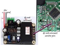
Hi, are you using the same power supply for transport and clock? If so you may need to disconnect the mid pin connection (gnd). Just connect to pin 64.
What voltage are you supplying the clock with? Make sure the clock power caps are rated at a higher voltage than the supply voltage..
The caps on my clock were 16v, and I was using the 17v supply to power it. I changed the caps to higher voltage rating..
Hi, are you using the same power supply for transport and clock? If so you may need to disconnect the mid pin connection (gnd). Just connect to pin 64.
-> So are u saying just connect Vcc of the clock to the transport only (at pin 64) and leave the middle pin ground open ?
What voltage are you supplying the clock with? Make sure the clock power caps are rated at a higher voltage than the supply voltage..
-> the voltage is DC 18V. I tap the supply before the peter regulator and supply it to the audio-gd clock. The audio-gd external clock requires unregulated power supply between 10-25V.
The caps on my clock were 16v, and I was using the 17v supply to power it. I changed the caps to higher voltage rating..
My caps are rated 35V
- Home
- Source & Line
- Digital Source
- Finally, an affordable CD Transport: the Shigaclone story