The pics you see were taken when testing with 2.2k/100R. The resistors were measured, and matched to 0.1% per Shaan's suggestion....Can you tell me what feedback configuration did you used on amplifier presend on your square wave test ?
2.2k/100R
or 1k/47R
Thanks
About bias stability.
The best way is allways to use as a tem sensor the same transistor type as an output transistor.
Fet -hex irfp version bias is rock solid (cold amp 100mA, very very hot amp is around 95mA).
BJT I am testing at the moment.
If someone is going to use darlington outputs than - please use small darlington to compensate bias.
Borys sorry for my off topic !
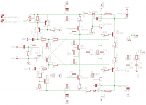
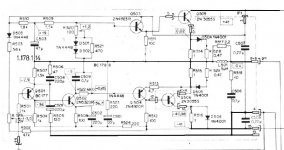
It is related to VAS (double) bootstrap technique issue , actually only AB class BJT SS Amp with acceptable good sonics for me it is my very old CFB singleton Revox A78 , on this my attached A78 simplified schematic you can see example of Revox solution for passive VAS bootstrap , done via resistive voltage divider consisted of two resistor R523 & R524 , where output signal is feed trough Elko C 510 .
I think that for DIY simetric CFB BJT Amp variant I need to implement four resistors and two Elkos with same values for that VAS double bootstrap passive network , practically done via two resistor & one Elko for top VAS stage , and two resistor & one Elko for bottom VAS stage .
Need your opinion !
Best Regards !
Attachments
Borys sorry for my off topic !
It is related to VAS (double) bootstrap technique issue , actually only AB class BJT SS Amp with acceptable good sonics for me it is my very old CFB singleton Revox A78 , on this my attached A78 simplified schematic you can see example of Revox solution for passive VAS bootstrap , done via resistive voltage divider consisted of two resistor R523 & R524 , where output signal is feed trough Elko C 510 .
I think that for DIY simetric CFB BJT Amp variant I need to implement four resistors and two Elkos with same values for that VAS double bootstrap passive network , practically done via two resistor & one Elko for top VAS stage , and two resistor & one Elko for bottom VAS stage .
Need your opinion !
Best Regards !
You have two options:
Option 1:
One cap + two resistors (high power rated 5W) cause You have to "feed rail voltage" back to psu - voltage drop on rail resistor. There is lots of heat generated in here. Resistors have to be 'low; in value
Option 2:
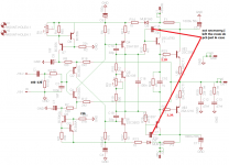
Cap + resistor + diode (like my one post 22 is schematic), resistor can be higher value an lower power rating, there is no need to ''feed the psu back with voltage'' --> diode. If we go further we can use 5v zener diode to keep bootstrapped voltage 5v over/under psu voltage.
Idefixes
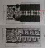
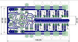
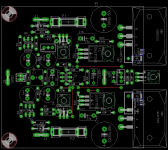
Very nice layout!!!
The small changes bellow
Attachments
Last edited:
Idefixes
Very nice layout!!!
The small changes bellow
Thanks for advices. I will test this after LC VSSA test with same PSU +/-35Vdc
Marc
Borys
Thanks for your clarification and advice !!!
I do not know If I was precise enough. Sometimes there is too much thinks in my head at the same time - sory.
Option 1 and option 2 are per voltage rail, so whole amp needs:
2caps
4 resistors
or
2caps
2resistors
2diodes
Hi Borys,
On BJT schematic you give a grade A for BC546 but nothing for BC556 on BC550/560 any advice to this?
Marc
All off BCxxx the best would be the highest grade - so if you can get C would be perfect if not B will do the job. Get highest grade anyway.
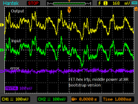
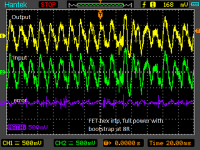
Borys, I may not be looking at these pics correctly, or not understand how the scale is set... the error "signal" looks much larger than it can possibly be, especially at the peaks in the violet trace on the display (?)Bellow fet-hex irfp. Yellow is output signal (taken from 10k potenciometer), green is input, violet is error signal.
Borys, I may not be looking at these pics correctly, or not understand how the scale is set... the error "signal" looks much larger than it can possibly be, especially at the peaks in the violet trace on the display (?)
The output signal is full amplitude scalled down to match input signal, tan I did A-B channel in scope and fiolet is result. I do not know if that kind of measurement is correct or not but I did it anyway.
I have measured thd at nearly full amplitude (40V -p-p) and they were exacly the same as for 20V p-p as I normally do the tests.
The peaks are prapobly due to bootstrap - I do not know. Monday I will test BJT version and compare.
I suspect your circuit is fine, but this particular pic/measurement/calculation, may not be. I just don't see the reason why.The output signal is full amplitude scalled down to match input signal, tan I did A-B channel in scope and fiolet is result. I do not know if that kind of measurement is correct or not but I did it anyway.
I have measured thd at nearly full amplitude (40V -p-p) and they were exacly the same as for 20V p-p as I normally do the tests.
The peaks are prapobly due to bootstrap - I do not know. Monday I will test BJT version and compare.
Perhaps you can expend the time base, and look at one or two waveforms at a time. Perhaps there is enough time lag in the data acquisition to make this look the way it does...

I suspect your circuit is fine, but this particular pic/measurement/calculation, may not be. I just don't see the reason why.
Perhaps you can expend the time base, and look at one or two waveforms at a time. Perhaps there is enough time lag in the data acquisition to make this look the way it does...
Hmm
That is good point - maybe the signals arent perfectly in phase. I will try to check.
- Home
- Amplifiers
- Solid State
- FET-hex explendit amplifier