jean-paul said:
Leave them one night in olive oil and put them in the oven for one hour at 200 degrees Celsius the next day. Totally different then.

And then freeze them at -180ºC for 48 hours.
Take them to room temperature very quickly under fire.
If they don't crack after this, they're good.

Microdynamics much better.

Hi Till, the scope may be part of the loop. Beware with scope grounded to the safety earth of the mains
I´m pretty sure it is part of a loop and it is of corse grounded as it ´has a 3 pin power plug. The noise i measure is not 50Hz but really HF like about 40 to 60Mhz / each day different distributions.
Also my impression is the power mains/null/ground lines are full of miracolous noise, null shows about 2V RMS against ground also they are connected at the house power inlet box.
What should i do? belive there is no problem? ok. If this is the way to build 18Bit DACs.
You are still missing the point
When you lay out a PCB, keep the loops small as to minimse EMI.
Look..........go out and buy some DAC kit......any kit. Build the silly thing. Get a good 'scope......>100 MHz. Learn to use it. (You are a student, right?)
Read Guido's article on grounding. Read it again. And once more. Lay out a simple board.......similar to your simple kit, using his techniques. Measure the two of them. Learn to identify what the differences are, and why they are there. Then decide if you need ferrite beads everywhere, and silly isolators.
What guys like Wilson and I do, and what you should be trying, are on different levels. You need to master the basics first......and I do not sense where you have by the nature of your questions.
You are not going to learn anything by trying to make something overly complicated.....and for no reason........when you are trying something more than you can handle.
You really don't think that we started out that way, do you?
Jocko
BTW......I see no reason why you can't keep the loops small just because it is SPDIF. The loop has to be small on ANY PCB to keep the EMI down. Read Guido's paper...................
- i don´t need to get a scope, i have two of them, one is TEK7904, what should be fast enough.
- I will not buy any silly DAC kit as the circuits in those kits with TDA1543 etc. i can get working now in about half an hour without need of kit. Did half a dozend of them. Waste of money only good for those who try to sell primitive circuit kits.
- i will not make a pretty silkscreen PCB for every experiment i do to go into competition with you and Per Anders who is able to make the prettyest looking PCB. I prototype and don´t build 10thousands. Also i condider a decoupling cap soldered p2p directly to the IC shorter than whats possible with PCB.
- I did read the article, i did read Horowitz Hill, and i did read some hundred datasheets and application notes from TI and AD
now. Sometimes i find one telling the plain opposite of the other... Of corse i do make shortest possible decoupling pass etc. were possible.
- "Loop" on topic at Jewilson´s suggestion for ISO150 was the connection of transport and reciver/DAC via spdif.
- I will try the ISO150 circuit as it is an experiment suggested with good reasons behind, in opposite to advice like [buy expensive resistor;buy monster cable; buy black gate cap; paint your nose green; put picture into freezer; lay stone on your head while listening; don´t ever do AB tests.]
- except those i recived via private mail until now the best answer on topic so far is that one from Charles Hansen. Thanks.
I just have to say, if you are seeing high frequency millivolt signals with a high-impedance scope probe, that noise is almost certainly coming from the scope itself and/or the probe, not from the circuit under test. I have a really nice Tek analog scope and it has self-generated noise of at least 5mV p-p. Trying to measure anything with the high-impedance probe and the vertical set to 20mV/div is fruitless.
If you want the real story on your circuit's behavior, try designing in some test points. There's several nice ideas for such probes in High Speed Digital Design. Or you could build a nice active differential probe.
If you want the real story on your circuit's behavior, try designing in some test points. There's several nice ideas for such probes in High Speed Digital Design. Or you could build a nice active differential probe.
Oh thank you so much, that is the statement i waited for. I had this impression. No matter what point i try to measure, if i got evrything possible away with filters and decoupling there stays something looking the same werever i measure.
Do i need an active probe connected to my high impedance plugin, does a high impedance differential amp help (i think not avaiable in high bandwith) or does a 50Ohm plugin do it?
Do i need an active probe connected to my high impedance plugin, does a high impedance differential amp help (i think not avaiable in high bandwith) or does a 50Ohm plugin do it?
Try here: http://www.sigcon.com/Pubs/straight/probes.htm
It describes the construction of a 21:1 attenuating passive probe for > 1GHz operation. For best results use the zero-length grounding (solder the braid directly to your circuit). Attach it to your scope's 50Ω input.
It describes the construction of a 21:1 attenuating passive probe for > 1GHz operation. For best results use the zero-length grounding (solder the braid directly to your circuit). Attach it to your scope's 50Ω input.
What's All This Ground Noise Stuff, Anyhow?
Maybe this article by Bob Pease explains what I meant.
http://www.national.com/rap/Story/0,1562,18,00.html
If your scope chassis is grounded and the amplifier/circuit under test also you have a huge groundloop not only picking hum but also HF. My scope is usuallly not grounded.
Hi Till,till said:
I´m pretty sure it is part of a loop and it is of corse grounded as it ´has a 3 pin power plug. The noise i measure is not 50Hz but really HF like about 40 to 60Mhz / each day different distributions.
Also my impression is the power mains/null/ground lines are full of miracolous noise, null shows about 2V RMS against ground also they are connected at the house power inlet box.
What should i do? belive there is no problem? ok. If this is the way to build 18Bit DACs.
Maybe this article by Bob Pease explains what I meant.
http://www.national.com/rap/Story/0,1562,18,00.html
If your scope chassis is grounded and the amplifier/circuit under test also you have a huge groundloop not only picking hum but also HF. My scope is usuallly not grounded.
Yes I know.jwb said:You should be aware that an ungrounded, or "floated" scope can be dangerous to the scope, the circuit under test, and the human operating them. Do not remove the scope's ground unless you know exactly what you are doing.
those links are great reading and i´m more and more convinced there is not much real noise at my DAC. I had resisual signals in the scope of about 10mV p2p after playing with decoupling and filtering using a high impedance probe and grounded scope with a gnd clip of ~200mm
All this because you might have probe noise?
In order to look at data lines......or anything HF......where a long ground lead on your 'scope is causing problems, get a HF probe tip. Like the one on this probe.
If you need a ferrite bead on your rails.............the type of bead you would use would look like the one shown. You don't need some overgrown bead that would go on a mains cable.
"Do I need a ferrite bead????"
Maybe.
"How do I know?"
It depends........
If you are suppling a handful of chips from one regulator, you probably do to prevent them from talking to each other. And without resonance problems that an inductor might cause.
One chip per regulator.......probably not.
Attachments
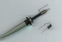
No.....you don't need a silkscreen.......solder mask.........or even a PCB to make a digital board. All you need is a piece of copper clad. Mount the chips upside down, with the ground pin bent over, and soldered directly to the copper. Works for DIP or SMT chips. You can use axial-, radial leaded or SM parts for bypass.......mounted in all manner of crazy ways......with the ground lead going right to the copper, and hopefully, a short lead to the supply pin.
Tag a piece of wire wrap to the signal pins. You can hold them down to the board with some hot melt glue. Small loop.......low EMI.
You don't think that I run out and make a PCB for every design without making one like this do you?? Maybe if I have made a lot that are very close, and I know that it will work, I might go direct.
OK..........you have a decent 'scope and some ratty DAC kits. You don't have to listen to them to learn something. Get one of the HF probe tips, and start measuring.
Now you have benchmark. Doesn't matter if it is a good or bad one.
Make a board of yours using the above technique. Measure it........compare the two.
If yours is better, now you know that you can do better than they did. Worse.......futz with it until it is better. No difference......now you know how many corners that you can cut and get away with.
You can learn something from taking anything apart. Either an example, or inspiration, for your own design if it is well executed. If it stinks, then you know how not to do it.
ok, thank for that usefull advice.
Iwill need to get a 50 Ohm plugin.
I use separate regulator for each IC.
I think i will not measure much noise and all claims about noise and beads may be more like paranoia, as those 10mV i measure with the normal probe may be picup noise, and with a HF probe i hace some attenuation of 10 or 20 :1 and will also not see more. The 50Ohm plugins are sensitive 10mV/1 and so i will not be able to see much with them in this low volatages.
I admit i build DACs and did not really listen to, like the TDA1543 experiments about inverting the dataline. But i don´t think listening is the right tool to detect noise on the DACs power supply.
Last days i intensively listen the balanced AD1865 DAC and AB with the build in TDA1305 of the transport.
ok, i recived a 50Ohm Y plugin for my scope today. Its a 7A24, i installed it in the 7904. I made some of those diy high speed probes from an 50 Ohm BNC connector, 1m RG174, and a 1k carbon composite resistor.
If moving this probe not connected to anything trough the air, in 1m around the DAC http://home.tu-clausthal.de/~tpa/space/mydac.jpg , i see some signal fom spdif on the CRT.
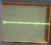
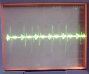
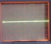
The power supplys measured at the input connectors of tzhe DAC board look like following, all with the 1:20 passive probe, 5mV/div setting for the 7A24, 50nS/div on the 7A80 timebase:
1st: CS8412CP digital and analog supply at 7805
If moving this probe not connected to anything trough the air, in 1m around the DAC http://home.tu-clausthal.de/~tpa/space/mydac.jpg , i see some signal fom spdif on the CRT.
The power supplys measured at the input connectors of tzhe DAC board look like following, all with the 1:20 passive probe, 5mV/div setting for the 7A24, 50nS/div on the 7A80 timebase:
1st: CS8412CP digital and analog supply at 7805
Attachments
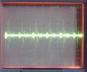
4th the AD1865 analog supply, zehner regulator from this thread http://www.diyaudio.com/forums/showthread.php?s=&threadid=30016&perpage=10&highlight=&pagenumber=3
only one side shown, +5V and -5V do look the same
only one side shown, +5V and -5V do look the same
Attachments
- Status
- This old topic is closed. If you want to reopen this topic, contact a moderator using the "Report Post" button.
- Home
- Source & Line
- Digital Source
- ferrite beads