finding hard specs for lossy beads is frustrating, the best you will find is impedance vs frequency plots at varying current levels, you can sometimes extrapolate the low frequency end of the graphs for a "L" value - it will typically be low, fractions of uH
lossy beads are used for attenuation of >> 1 MHz frequencies, inductors and chokes are better described by a finite "L" value < 1 MHz but are limited by their self resonant frequency
http://www.steward.com/Technical_Info.asp may help
lossy beads are used for attenuation of >> 1 MHz frequencies, inductors and chokes are better described by a finite "L" value < 1 MHz but are limited by their self resonant frequency
http://www.steward.com/Technical_Info.asp may help
You need to stop thinking of ferrites as coils, chokes, or inductors.
They are lossy materials that exhibit a resistive effect when inserted into a circuit. If you know the frequency range that you are trying to eliminate, then you look for a bead with the right mix.
You most likely want a 43 type material for what I assume you trying to do. Maybe a type 29, but they are not common. Type 73 is common, but probably not what you want. (They work in some types of output stages....................)
Fair-rite probably has web site explaining all of this.
Jocko
oh thanks, now i start to understand something about this.
What i want is a power supply as good as possible without much effort in multilayer PCB and this, so i get some of those 18Bit resolution of the AD1865, and not only 10 or 12...
As i understand i need a clean power supply as else the noise may be higher than the lower Bits. Also i thought with HF on the power line some IMD may disturb my audio signal, and this may be a reson to filter HF away ( from were ever the HF may come)
so i could get material 43 like small toroids, inner diameter 0.05 mm and outer 5.80 by 1.52mm, or material "ferroxube 3b" small cylindrical beads diameter 3.5mm, lenght 3; 5 or 7,5mm and a hole of 1,3mm.
I assume the last are right?
http://www.sigcon.com/Pubs\edn\ferritebeads.htm
http://www.bytemark.com/products/ferbead.htm
http://www.antennex.com/shack/Dec99/beads.htm
http://www.catchnet.com.au/~rjandusimports/tut_9a.html
Google has more answers than you can ask questions...
http://www.bytemark.com/products/ferbead.htm
http://www.antennex.com/shack/Dec99/beads.htm
http://www.catchnet.com.au/~rjandusimports/tut_9a.html
Google has more answers than you can ask questions...
Till,
I'm not sure if others have made it clear. At these very high frequencies there is enough capacitive coupling between adjacent turns in any multi-turn device to make it ineffective.
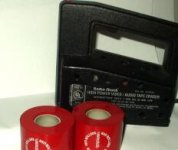
Regarding ferrites, I would avoid them at all costs. In my experience they do more harm than good sonically. This is hard to get a handle on because when you first put them in the circuit, they do sound good. But over time they become magnetized and harm the sound. So they have the unusual property of making your circuit sound better when you put them in, and again sound better when you take them out. This effect is easily demonstrated by demagnetizing any ferrites in your audio system with a bulk tape eraser.
If you want to achieve good isolation, one of the easiest, cheapest, and best sounding things is to use C-R-C pi filters. That assumes that you are working with low-current circuits (not power amps) and that the added R is tolerated.
Good luck, and don't forget to listen to what you build.
I'm not sure if others have made it clear. At these very high frequencies there is enough capacitive coupling between adjacent turns in any multi-turn device to make it ineffective.
Regarding ferrites, I would avoid them at all costs. In my experience they do more harm than good sonically. This is hard to get a handle on because when you first put them in the circuit, they do sound good. But over time they become magnetized and harm the sound. So they have the unusual property of making your circuit sound better when you put them in, and again sound better when you take them out. This effect is easily demonstrated by demagnetizing any ferrites in your audio system with a bulk tape eraser.
If you want to achieve good isolation, one of the easiest, cheapest, and best sounding things is to use C-R-C pi filters. That assumes that you are working with low-current circuits (not power amps) and that the added R is tolerated.
Good luck, and don't forget to listen to what you build.

ok, so i have a dozend of beads. Cylindrical, hole 1,3mm, D= 3,5mm height some 3, some 5 and some 7,5mm . Material is " ferroxube 3b ".
Should is use a lot of shorter or less of the longer ones on each line? Should i use them on a) only + and - voltage line, b) on ground also, c) on analog and digital supply or only analog, d) only on the power lines or also on signal between DAC chip and I/V converter stage ?
for the special kind audiophile gurus: e) do they sound better if painted green?
for the special kind audiophile gurus, do they sound better if painted green?
Leave them one night in olive oil and put them in the oven for one hour at 200 degrees Celsius the next day. Totally different then.
You can combine this action together with baking a pizza if you like. Don't eat the bead however.
hysteresis loops
"You are saying that the magnetic properties of a FERRITE changes do to DC"
The last time I looked they did ............
From: http://hyperphysics.phy-astr.gsu.edu/hbase/solids/hyst.html
" When a ferromagnetic material is magnetized in one direction, it will not relax back to zero magnetization when the imposed magnetizing field is removed. It must be driven back to zero by a field in the opposite direction."
From: http://www.coilws.com/magneticandhow.html
"So, it is very important in a choke or inductor design, not to drive the core into saturation by increasing the current (AC or DC). Usually it is the DC current that saturate the cores since it is a constant current, and puts the cores to a certain flux level."
A another description of the Hysteresis Loop at:
http://www.ndt-ed.org/EducationResources/CommunityCollege/MagParticle/Physics/HysteresisLoop.htm
Mag nags
"Actually they sound best when you leave them in your drawer, far away from your audio system..."
Except for my Versalab Red Rollers.........
Better take those pulse transformers out of the digital interface.
My point is there are places for ferrite materials in audio systems. You have to know the characteristics of the materials and how they are used. I thought everyone owned a bulk tape eraser for demagnetizing the materials in their audio circuits. Mine has has cooling holes drilled in the case to use it longer before the thermal breaker kicks in.
Attachments
Actually they sound best when you leave them in your drawer, far away from your audio system...
as nobody wants to answer my question this may be the best suggestion until now. But do you really say they affect sound in a bad way when used in the spdif recivers power supply? or only on analog circuit?
Anyway, i would prefer to try it out for scientific reasons, but better to know the right way how to use them before.
Where you use them depends on how you want to use them.
i did not knew they have more than one puprose. The only real case of ferrite bead use i know uses one big bead around all lines and is used at computer interconnects (monitor cables etc). I want to use because if you post on this board you built a DAC and it works, people do replay :"use ferrite beads" and do reply " do not ever use ferrite beads" , so there is one solution to use them and not use them to see what happens. As the ferrite bead is not obvios scum like some other things people here tell you to do it may serve a real purpose, to keep away noise from my circuit. Mainly to keep it away from traveling from the digital part where i expect a lot of noise to be as a normal fact into the analog section of the DAC and into the following amplifing and "probably mixing" stages where i don´t want it.. A lot of postings on this board contain the word ferrirtes, but there is not much hard information. I find the information they to work but not how to use them, sorry. Maybe i do not really need them and better use this approach to separate wanted from unwanted signals in the different parts of the DAC:
http://www.diyaudio.com/forums/showthread.php?postid=395618#post395618
Attachments
Why do you insist on making life diffiicult???? Get rid of those silly isolators. Expensive part that you don't have a problem that they are a solution for.
If you are tyring ot eliminate EMI.......which seems to be what you are aiming for.........even though you don't seem to grasp why......it is best to......
Keep the loop as small as possible.
That will solve a lot of your problems, without the need for stuff that you are not proficient in.
Yet. Learn the basics, before you try to conquer the mountain.
Jocko
Keep the loop as small as possible.
ok, will do in the final version. Not easy while using spdif.
you don't have a problem that they are a solution for.
nice to hear the problem is not there, why did jewilson tell me in the other thread it is?
I can´t estimate if the AC i see on the scope does harm the DACs precision or not. But i know the noise i see on the scope does not get less with other/different/better decoupling, more or less filters in the power supply lines or what else i did try. May be there is no way to measure less noise as it strays in every piece of metal i connect the pobe to. What i could do is measure THD/IMD via FFT what is a stable kind of meausurement and test with different approaches against noise. Such as complete isolation of power supplys. I don´t know if it will cause any diffrence, as nobdy tells me i can only try.
by the way, as nobody seems to be able to show valid measurements of all those fancy clock circuits around on this board: may they also be solutions for a problem not there?
Scope
Hi Till, the scope may be part of the loop. Beware with scope grounded to the safety earth of the mains

till said:
ok, will do in the final version. Not easy while using spdif.
nice to hear the problem is not there, why did jewilson tell me in the other thread it is?
I can´t estimate if the AC i see on the scope does harm the DACs precision or not. But i know the noise i see on the scope does not get less with other/different/better decoupling, more or less filters in the power supply lines or what else i did try. May be there is no way to measure less noise as it strays in every piece of metal i connect the pobe to. What i could do is measure THD/IMD via FFT what is a stable kind of meausurement and test with different approaches against noise. Such as complete isolation of power supplys. I don´t know if it will cause any diffrence, as nobdy tells me i can only try.
by the way, as nobody seems to be able to show valid measurements of all those fancy clock circuits around on this board: may they also be solutions for a problem not there?
Hi Till, the scope may be part of the loop. Beware with scope grounded to the safety earth of the mains
- Status
- This old topic is closed. If you want to reopen this topic, contact a moderator using the "Report Post" button.
- Home
- Source & Line
- Digital Source
- ferrite beads