I am not a fan of Acronyms.
Why?
They can be so confusing.
NBA . . . the National Benevolent Association, or what most of you know, the National Basketball Association.
AMA . . . the American Management Association, or what most of you know, the National Medical Association.
Were you surprised?
Test Your Ability (TYA):
When is an FLA not a three letter acronym?
When it is a Four Letter Acronym, Five Letter Acronym, Forty Letter Acronym, Fifty Letter Acronym, etc.
Now do you begin to understand the confusion?
So, come up with your own deciphering of an SEU.
How many three word combinations have the first letters of S, E, and U?
It would be SE-STP ...SE Screen Tapped Pentode. There's no shame in calling the output, screen tapped. If you want to sweep history under the rug along with whatever dirt, then just ignore the hisory of the pioneers and keep calling any screen tapped output, UL. If it's just more convenient, then it's wrong. If it's through following the hampster trail onto the wheel driving the hampster sausage machine... then that's a shame of not doing the research into history of the term UL and knowing the significance of it to our hobby and everyday application of historical terms.
George, and all readers of this thread,
(Load Pull mentioned at the bottom).
WIDWIO . . .
"When In Doubt, Write It Out"
WIULNUL
"When Is Ultra Linear Not Ultra Linear" . . . It is Not Linear at all, when the load is not a proper resistance load resistor.
Adding global negative feedback, may, or may not, help.
The same is true for many other output stage topologies. Adding global negative feedback, may, or may not, help.
Design an amplifier to work properly into a proper load resistor. That makes it easy to compare amplifiers (when they are loaded by a proper load resistor).
Or, design an amplifier to drive a loudspeaker. That is a completely different design problem.
And, comparing amplifiers by using real loudspeaker loads, is a completely different problem.
Bursted Spectral Measurements are in order.
If it were easy, you would all be doing it in your garage.
Hey George (you know who you are), I just thought about Load Pull Measurements!
Cell Station Power Amplifiers anybody?
Just Sayin'
Last edited:
"I just thought about Load Pull Measurements!"
I spent far too much time trying to get dynamic impedance measurements on a loudspeaker that's being driven with real music at various volume levels. I was convinced that a 15 inch woofer could exhibit a negative impedance while being pushed to near X-max with a sine wave at its resonant frequency and a large transient tries to instantly reverse its motion. These experiments led me too far down a rabbit hole that I will not go down again. Fortunately, I quit with most of my sanity intact. No valid conclusions were drawn.
"Cell Station Power Amplifiers anybody?"
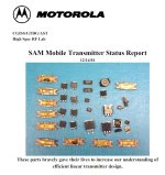
Been there done that. Here is Tubelab's other life......the one that paid the bills. 41+ years at Motorola starting on the HT-220 assembly line, leaving as a Principal Staff Research Engineer after collecting two engineering degrees, mostly at Motorola's expense. Yeah, I got paid well to blow stuff up there too!
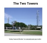
Load pull tests on a potentially unstable amp can make flaming parts. The last photos show the cover of two reports I wrote. Sometimes it's hard to get management to even read the reports that they spent a boat load of money on. This one, and most of my others got their attention. Yeah, I worked on FM receivers too. that report was written at the time when a big movie with the same name hit the theaters. The nose of my white Mustang can be seen in the picture.
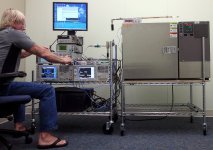
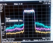
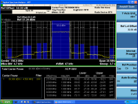
these experiments involve a 5 MHz wide LTE transmitter at 795 MHz with 100 watt peaks having a 10 dB peak to average ratio (sometimes called crest factor in the audio world). Dynamic pre-distortion being tested over temperature and load pull conditions. Trombone line (variable length 50 ohm line) and box full of assorted mismatched loads on top of temp chamber. Scintera pre distortion chip test at room temp with a 50 ohm load (the control, or known good condition). Quick response analyzer on right sees quick bursts of unwanted energy when the load is varied. A "Trombone Line" is "pulled" (hence the name load pull) to vary the phase of the load mismatch. Yellow is input to power amp. Blue is uncorrected output. Pink is with pre-distortion engaged. Better analyzer on left measures the Adjacent Channel Power that leaks into the nearby RF channels due to IMD. It will calculate the amount of leakage that's seen on the quick response analyzer. These analyzers look at the frequency VS power level of an RF signal. Just as a speaker is almost never an "8 ohm" purely resistive load, an antenna on an RF transmitter is not 50 ohms resistive. The load impedance varies as anything in the surroundings move, and it must eat some of the output from all the other transmitters in the vicinity of the antenna.
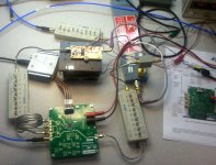
Top secret (as of 2011) Scintera chip test with 10 watt Peak RF Power Amp. Scintera was gobbled up by one of the bigger fish in the chip business after it was shown that their stuff worked.
I spent far too much time trying to get dynamic impedance measurements on a loudspeaker that's being driven with real music at various volume levels. I was convinced that a 15 inch woofer could exhibit a negative impedance while being pushed to near X-max with a sine wave at its resonant frequency and a large transient tries to instantly reverse its motion. These experiments led me too far down a rabbit hole that I will not go down again. Fortunately, I quit with most of my sanity intact. No valid conclusions were drawn.
"Cell Station Power Amplifiers anybody?"
Been there done that. Here is Tubelab's other life......the one that paid the bills. 41+ years at Motorola starting on the HT-220 assembly line, leaving as a Principal Staff Research Engineer after collecting two engineering degrees, mostly at Motorola's expense. Yeah, I got paid well to blow stuff up there too!
Load pull tests on a potentially unstable amp can make flaming parts. The last photos show the cover of two reports I wrote. Sometimes it's hard to get management to even read the reports that they spent a boat load of money on. This one, and most of my others got their attention. Yeah, I worked on FM receivers too. that report was written at the time when a big movie with the same name hit the theaters. The nose of my white Mustang can be seen in the picture.
these experiments involve a 5 MHz wide LTE transmitter at 795 MHz with 100 watt peaks having a 10 dB peak to average ratio (sometimes called crest factor in the audio world). Dynamic pre-distortion being tested over temperature and load pull conditions. Trombone line (variable length 50 ohm line) and box full of assorted mismatched loads on top of temp chamber. Scintera pre distortion chip test at room temp with a 50 ohm load (the control, or known good condition). Quick response analyzer on right sees quick bursts of unwanted energy when the load is varied. A "Trombone Line" is "pulled" (hence the name load pull) to vary the phase of the load mismatch. Yellow is input to power amp. Blue is uncorrected output. Pink is with pre-distortion engaged. Better analyzer on left measures the Adjacent Channel Power that leaks into the nearby RF channels due to IMD. It will calculate the amount of leakage that's seen on the quick response analyzer. These analyzers look at the frequency VS power level of an RF signal. Just as a speaker is almost never an "8 ohm" purely resistive load, an antenna on an RF transmitter is not 50 ohms resistive. The load impedance varies as anything in the surroundings move, and it must eat some of the output from all the other transmitters in the vicinity of the antenna.
Top secret (as of 2011) Scintera chip test with 10 watt Peak RF Power Amp. Scintera was gobbled up by one of the bigger fish in the chip business after it was shown that their stuff worked.
Attachments
"You know you're good when they let you wear flip flops at work"
They enforced a "closed toed shoes in the factory policy" in the 70's and early 80's. By the mid 80's there were too many people from India and the middle east working there who wore sandals, and the factory no longer built anything larger than a walkie talkie or cell phone, so that policy might have been still on the books but wasn't enforced. Flip flops were pretty common as we WERE in south Florida. So were shorts and a tank top in the summer. The building where I worked was not near what was left of the factory and was for the most part uninhabited. Let's just say that there was more than one person in our lab that ran around barefoot for a couple years. These pictures were taken during the reconstruction of our building for the plant's eventual sale. Flip flops were needed due to scattered construction debris like sheetrock screws and broken glass. The plant was sold before I left and Chewy, the dog food company now occupies that building and the other "engineering building." Motorola still leases a part of the original factory building. Somewhere between 200 and 500 people work there now. There were over 5000 in its heyday.
Return to the subtract traces mode. You should now have a display of just the amp's distortion. Remove the signal generator and connect a suitable music source. Ideally you should see nothing but a flat line. This won't be the case especially as the volume is increased. If the results seem reasonable, remove the 8 ohm resistor and connect a speaker. Prepare to be surprised. Play some DSOTM and crank it. Plug in a guitar and connect a guitar speaker, pick some notes near the speaker's resonance. Surprised yet?
They enforced a "closed toed shoes in the factory policy" in the 70's and early 80's. By the mid 80's there were too many people from India and the middle east working there who wore sandals, and the factory no longer built anything larger than a walkie talkie or cell phone, so that policy might have been still on the books but wasn't enforced. Flip flops were pretty common as we WERE in south Florida. So were shorts and a tank top in the summer. The building where I worked was not near what was left of the factory and was for the most part uninhabited. Let's just say that there was more than one person in our lab that ran around barefoot for a couple years. These pictures were taken during the reconstruction of our building for the plant's eventual sale. Flip flops were needed due to scattered construction debris like sheetrock screws and broken glass. The plant was sold before I left and Chewy, the dog food company now occupies that building and the other "engineering building." Motorola still leases a part of the original factory building. Somewhere between 200 and 500 people work there now. There were over 5000 in its heyday.
There are some measurements that can be made with real music and real speakers. You will need a scope that has the ability to subtract one channel from the other and display the result, preferably a storage scope. My ancient 1990 vintage Tek 2232 will do it, but it is not obvious from the front panel. You use the ADD mode to add trace 1 to trace 2 and display the result. Then press the invert button on trace 2. Connect the two probes to your audio gen at a level needed to push the amp to a loud volume. Adjust the knobs to on the scope to get a flat line indicating that the difference between the two traces is nil. Connect the generator to the amp's input and verify that you still have a flat line. With a suitable load desistance attached to the amp, and an attenuator between the amp scope, move one of the probes to the attenuator's output and adjust the attenuator for as flat a line as possible. I use a 500 ohm pot and a series resistor (2K, 2 watt) wired across the 8 ohm load for my attenuator. Start with the pot set for zero output (wiper at the ground end) and increase the level to match the amps input. Sometimes it's best to do this in the scope's normal mode to get identical traces, then subtract them. If the traces are not in phase because the amp inverts the signal, then you won't need to invert trace 2.Or, design an amplifier to drive a loudspeaker. That is a completely different design problem.
And, comparing amplifiers by using real loudspeaker loads, is a completely different problem.
Bursted Spectral Measurements are in order.
If it were easy, you would all be doing it in your garage.
Return to the subtract traces mode. You should now have a display of just the amp's distortion. Remove the signal generator and connect a suitable music source. Ideally you should see nothing but a flat line. This won't be the case especially as the volume is increased. If the results seem reasonable, remove the 8 ohm resistor and connect a speaker. Prepare to be surprised. Play some DSOTM and crank it. Plug in a guitar and connect a guitar speaker, pick some notes near the speaker's resonance. Surprised yet?
Tubelab_com,
Unique Audio test measurement?
I always wanted someone to take a high bit count Arbitrary Wave Generator, and do the math to load a special signal.
16 QAM, symbol rate 300, root raised cosine filter, and a "carrier frequency" of 1kHz, for example.
Then use a good baseband spectrum analyzer to look at the upper adjacent channel, and lower adjacent channel levels.
Lower adjacent 550 to 850Hz, main channel 850 to 1150Hz, and Upper adjacent 1150 to 1450Hz.
Given the right order of QAM, the right filter, etc.; it might have a large enough peak to average level, to do testing at high peak power levels to a loudspeaker, but with low rms values to prevent loudspeaker driver burnout.
Just a wild idea.
That would be a neat experiment. Unfortunately, I lost access to all the fancy test equipment in 2014 when I retired and moved 1200 miles north. I used to visit the plant, or what's left of it every year on my summer road trip but haven't been that far south since Covid came. Most of that high $$ HP stuff had a lower frequency limit of about 100 KHz, but something could be rigged up with mixer and some filters. Some had baseband inputs, but they were an option that we rarely had. Those were reserved for the DSP guys who resided in a different building. The plant had 5 buildings totaling nearly 1 million square feet. It has now literally gone to the dogs!
Which is why measuring/designing into a fixed resistive load in just the starting point. I've made changes to an amp that clearly were a sonic improvement, but measured worse into a dummy load. There is a reason they are called a dummy load.The same is true for many other output stage topologies. Adding global negative feedback, may, or may not, help.
Design an amplifier to work properly into a proper load resistor. That makes it easy to compare amplifiers (when they are loaded by a proper load resistor).
Or, design an amplifier to drive a loudspeaker. That is a completely different design problem.
And, comparing amplifiers by using real loudspeaker loads, is a completely different problem.
")
- Home
- Amplifiers
- Tubes / Valves
- Feasibility of getting 15W out of a SET tube design?