rajeev luthra said:K-Amps
How can I get 1200w in bridge mode with +/-72vrails ????
Rough estimates.
72vdc is about 51v RMS. Take away 2 volts for circuit losses and about 3-4 volts rails sagging and you get 44volts RMS. This is about 242 watts 8 ohms. Practically you get 1.5x power into half the load (1.66x with extra large trafos... again roughly).
So at 4 ohms you get 400 watts and at 2 ohms 600 watts per channel.
If you bridge into 4 ohms, you get twice the 2 ohm rating of a single channel so 600 x2 = 1200 watts bridged into one single 4 ohms bridged channel.
This is doable... as long as the trafo is well regulated and trannies kept cool.
For 500 into 4 ohm, you are looking at rails of around +/- 84 at the minimum. Unless you have a dedicated 1kVA per channal then +/-80 might work too.
I have used Avel 1kVA's (800va's too) into a single channel with +/-86 vdc and get 350 watts into 8 ohms and 550 into 4 ohms. However My AC mains is via a 25 foot extension cord which drops like 7-8 volts AC under load and my mains drop to 113v from 121v.
So theoratically for a similar BJT circuit as the one I am using, with rock solid AC mains, +/-80vdc should do it with an excellent and well regulated power Supply. Not knowing how efficient your own made transformer is, these numbers may or may not work.
Hi,
Sorry , at present I do not have acess to the net due to a local problem here at my end hence I have not been able to post , today I am doing the same from another place .
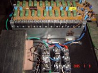
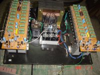
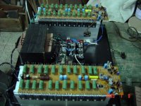
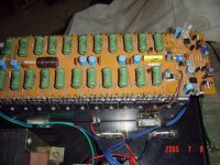
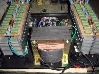
I have completed both channels of my amp now and am posting some construction pictures , at present there are only 6 x 10,000 mfd caps , I will be adding another 6 after I get them , you can see size of heatsinks , there are also two four inch cooling fans running at full speed which I have fitted in the back cover hence they are not in the pictures ,
K-Amps
If I can get 1200w at 4 ohms in bridge at the present supply voltages , 1600W at 2 ohms bridge mode should not be a problem . However I will use this amp in stereo mode for some time first .
I also realise that it will be better to make a single channel high power amp next time so that I can give it max current from my custom made transformers and also reduce the overall size .
Jacco
Thanks for your post ,
you write
" Under normal operation there will be current going through the devices half of the cycle time, the other half of the sinus the non-active devices and their emitter resistors cool down..
In bridged mode you'd have current going through two banks of output devices and emitter resistors all the time.
With current being twice as high in bridged operation thermal issues should be considerable, as it goes through the output of both channels at once, thermal load on each channel is 4 times higher or more.
With the temperatures you posted of Indian conditions you would need some very serious cooling, Rajeev.
I gathered it is not that easy to have an amplifier stable at 1 ohm operation unless it is designed for such impedance from the start."
Now after seeing the pictures I hope you will be satisfied with the cooling arrangement , also there is no insulator between the output transistors and the heatsinks , the heatsinks are the rails and the same have been insulated from the chasis .
Worst case tempratures in Indian conditions are not above 35 digrees , at least not in my city , I think you have in mind the tempratures quoted by Ampman who lives on the SUN , I think???? .
The Leach Amp design is very stable even below 1 ohm , I have one working at 1 ohm since over a year and no problems , this is why I love the design , if you like I will post a pic of the same too .
Richie
Andrew T
Yes the losses are more in bridging , I think at the present supply voltages of +/- 72v the nos of devices in the output ( 11 pairs per channel ) are enough for the amp to operate in bridgemode up to 2 ohms , however as a caution as said eirlear I will use this amp in stereo mode for some time first .
THANKS
Sorry , at present I do not have acess to the net due to a local problem here at my end hence I have not been able to post , today I am doing the same from another place .
I have completed both channels of my amp now and am posting some construction pictures , at present there are only 6 x 10,000 mfd caps , I will be adding another 6 after I get them , you can see size of heatsinks , there are also two four inch cooling fans running at full speed which I have fitted in the back cover hence they are not in the pictures ,
K-Amps
If I can get 1200w at 4 ohms in bridge at the present supply voltages , 1600W at 2 ohms bridge mode should not be a problem . However I will use this amp in stereo mode for some time first .
I also realise that it will be better to make a single channel high power amp next time so that I can give it max current from my custom made transformers and also reduce the overall size .
Jacco
Thanks for your post ,
you write
" Under normal operation there will be current going through the devices half of the cycle time, the other half of the sinus the non-active devices and their emitter resistors cool down..
In bridged mode you'd have current going through two banks of output devices and emitter resistors all the time.
With current being twice as high in bridged operation thermal issues should be considerable, as it goes through the output of both channels at once, thermal load on each channel is 4 times higher or more.
With the temperatures you posted of Indian conditions you would need some very serious cooling, Rajeev.
I gathered it is not that easy to have an amplifier stable at 1 ohm operation unless it is designed for such impedance from the start."
Now after seeing the pictures I hope you will be satisfied with the cooling arrangement , also there is no insulator between the output transistors and the heatsinks , the heatsinks are the rails and the same have been insulated from the chasis .
Worst case tempratures in Indian conditions are not above 35 digrees , at least not in my city , I think you have in mind the tempratures quoted by Ampman who lives on the SUN , I think???? .
The Leach Amp design is very stable even below 1 ohm , I have one working at 1 ohm since over a year and no problems , this is why I love the design , if you like I will post a pic of the same too .
Richie
Andrew T
Yes the losses are more in bridging , I think at the present supply voltages of +/- 72v the nos of devices in the output ( 11 pairs per channel ) are enough for the amp to operate in bridgemode up to 2 ohms , however as a caution as said eirlear I will use this amp in stereo mode for some time first .
THANKS
Rajeev,
1) Looks not too bad.
2) If the Sinks will have a fan, then they look adequatly sized.
3) The power supply seems a tad anemic (unless you have a second trafo/ cap bank in the empty space yet to be installed)
4) If it were me, I'd use about 80,000uF for this amplifier per rail or 160,000uF in total if you want to hit the power levels you wish for. (Less will work too but at reduced power into music).
5) In the US we have 120v but higher current rated mains. In India, I reckon with all the rapid growth going on, keeping a steady 220v might be challenging, let alone keeping 220v with the amplifier running at full power... this is just a thought, you probably know better.
6) If you ask me, you will probably not hear the difference between 1200 watts and 1400 watts so I'd go with a reliable amp than a hi-powered version perhaps prone to break-down.
7) Probably too late now? But All your transistors are mounted at the top of the heatsink. Don't shoot me down for this, but I think heat travels up better than travelling down a heatsink, just consider this when testing the amp. The last thing you want to happen to your amp is it thermally shutting down during a performance.
(Which reminds me, what rating thermal switches are you using?)
thanks!
K-
Hi K-Amps,
Sorry for the late reply , my internet connection had expired but it is ok now
.
Yes I will be adding another bank of caps ( I have to get them from Delhi
or Mumbai they are not availible locally ) You recomended 80,000uf per
rail , will a 35A bridge rect handle the initial charging current of such high
value cap banks ? .
Yes the voltages do vary with load , specially when we do outdoor events
where we have to get a temperory connection .
With cooling fans it does not matter if the devices are mounted up or
down , and fortunately the temp of the heatsinks is not going too high ,
there is NO provision for high temp shutdown in my amp , it will be only
required if the fans fail , this is the reason I have used extra large
heatsinks so that the amp will silll work but hotter , and normally we see
every time if the fans are on , further it is a DIY amp , I have done more
than my competancy but thanks for the concern you are showing .
...........I think heat travels up better than travelling down a heatsink............
Hi K-amps ,
You should have elaborated more on this.
Heat goes up or down through metal at the same rate. However in a heat sink the air flow is upward and That affects the heat transfer. But if you look at it closely , since heat transfer is greater when the temperature difference is larger , the bottom section should have better heat transfer ( be cooler ). As the heated air travels up its cooling will reduce as it is now hotter than at the bottom and the top of the heatsink should be hotter than the bottom section.
If a fan is used this effect should be less , the difference in temperature being less with increasing air flow.
So transistors mounted lower than mid way seems to be OK.
Sounds OK ?
Rajiv,
If your heat sinks are placed like in the second picture with the pcb on top , your heat sinks will be less efficient. Even without the pcb on top the fins in a horizontal position will cool much less than if they were vertical and followed the natural flow of air.
Remember you did consider the possibility of fan failure and the need to operate the amp under that condition also. In any case two fans is a must to ensure 'some' air flow even if one fails. Both fans failing at one time is a remote possibility . A set of fans cooling both banks of heat sinks with redundant power to the fans might be a safe thing to do.
Cheers.
Rajeev,
one last time, just for you:
http://www.electronics-cooling.com/Resources/EC_Articles/MAY96/may96_01.htm
Paragraph: consider multiple fans.
If you can, have the props rotate in different directions.
This will reduce noise, and increase efficiency.
For reference:
the cruiseship QE2 uses this for the propulsion screws, saves a lot of fuel and reduces vibration.
Propellors airplaines have contra-rotating dual props too, also less noise, better fuel efficiency.
Gas turbine engines make use of this approach as well.
jacco vermeulen said:Propellors airplaines
-s, -i.

Your high power amplifier looks very impressive, Rajeev.
Thank you for posting the many great pictures.
Hi Jacco,
Thanks for the link,
I am planning of using a autotransformer in the output of the amp with a ratio of 1; 1.5 , hence I will get the desired power at 4 ohms without bridging or increasing the supply voltage , what are your comments
( if the output is 40v with transformer it will be 60v )
Thanks for the link,
I am planning of using a autotransformer in the output of the amp with a ratio of 1; 1.5 , hence I will get the desired power at 4 ohms without bridging or increasing the supply voltage , what are your comments
( if the output is 40v with transformer it will be 60v )
- Status
- This old topic is closed. If you want to reopen this topic, contact a moderator using the "Report Post" button.
- Home
- Amplifiers
- Solid State
- Favorite High Power Output Transistor