K-amps
Don't fret. The toroids were made for me with absolutely identical windings with 5% regulation and it worked a treat. No ill effects as sufficient and equal impedances.
Rajeev,
You will need to increase those 330 resistors from 220 with 2xVbe to Vgs of maybe 4V i.e. more than 3 times 220.
Also 2.5A is at zero crossing on you rail voltage unless you're well into pulse region.
The output stage is wasteful as Vgs at >6V on will lose output. If you used a CFP with gain you would only have Vds at 2V or less. But you need complements. Sometimes cheap is not so good.
Rajeev,
seems to me a good idea to switch to Mosfets, given your requirements.
Especially if the IRFP250 price is that low in India.
What i do not understand is how you will use them for a push-pull design ?
Complementary matching of vertical Mosfets is quite bad, to me it looks that these high power Mosfet types are generally good for single-ended use only.
You intend to use IRFP250's on both sides ?
The Silltech guys overhere did a hybrid Mosfet amplifier a long time ago.
It ran on doubled multiple secondaries transformers for the outputs, could be switched in 100 watt class A in 2,4,6,8 Ohms by pushing a button on the front that put the secondaries in parallel or series.
amplifierguru said:K-amps
Don't fret. The toroids were made for me with absolutely identical windings with 5% regulation and it worked a treat. No ill effects as sufficient and equal impedances.
I guess a custom Toroid would work... what did you use for switching?
Rajeev, I have not worked with MOSFETS, Jacco and Ampguru can help u there.
The Toshibas also cost equal to $ 1.00 here ,
I am trying to use the IRFP250 because of their availibility and good specks along with low price , I just took parts from different designs and added them , if they work there , I do not see why they should not work here , I will make a model with two output devices and see .
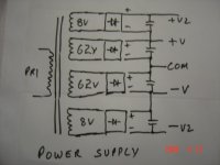
here is the power supply
I am trying to use the IRFP250 because of their availibility and good specks along with low price , I just took parts from different designs and added them , if they work there , I do not see why they should not work here , I will make a model with two output devices and see .
here is the power supply
Attachments
hello paaji
Hi Rajeev,
I am afriad that the output swing will clip asymmetrically.
The positive side will clip near rail but the negative side will remain 3-4 volts lesser than rail, Although you have used seperate supplies for VAS and output stage, but the lower P-channel mosfet will enter the band-gap mode thus restrict the negative rail swing upto the rails.
regards,
Kanwar
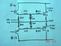
Ampman ,
The output stage is from the Zeta , if you see carefully , the output stage
is symetrical , at low levels the output in the -ve side is from IRFP9240
only and as the power increases the IRFP250 take the load ,
to simply explain I made this diagram , see in attachment
The output stage is from the Zeta , if you see carefully , the output stage
is symetrical , at low levels the output in the -ve side is from IRFP9240
only and as the power increases the IRFP250 take the load ,
to simply explain I made this diagram , see in attachment
Attachments
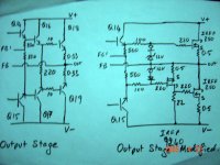
AndrewT said:Hi workhorse,
is it that simple to solve the Nchannel asymetric clippng. Run the lower driver off the +Vrail
Hi Andrew,
The story dates back to 6 years ago when i was designing quasi Complementary bipolar amps. At that time one of our friend came to me and suggested me to use n-channel mosfets at the output, since he was using them in his Induction Furnances. Then i took the mosfets irf540n and implemented them in place of 2N3773 bipolar with a little modification to circuit to assist gate voltage. The bipolar design was giving 100W at 8 ohms , whereas mosfet amp was just touching only 78W at 8 ohms, Due to the rail loss created by the high gate threshold voltage. Then after investigating the case i implemented THIS technique and the output voltage just swing to its rails. Quite happy at that time.
")
But this technique has low damping factor also. Thats why i prefer to abandon this technique at that time and started searching other alternatives and now we have the best alternative with us which we use in our amps.
that's all, hope you enjoyed my little story.
regards,
kanwar
High Power Leach Amp
Hi friends,
I have finally compleated one channel of the leach amp with rails +/- 72v (
50v-0v-50v transformer ), eleven pairs of Toshiba 2SA1943/2SC5200 in
the output , as per K-Amps advise I have lowered the supply voltage , I
tested with an input of Dance music from a CD , it really sounded very
very good even at po max at 8 ohms around 250w the sound was very
clear , very good bass also there was no heating because of the large
heatsinks without the cooling fan which I will be adding later, I have to
further test it at 2ohms , here the power output should be around 1000w .
Now I am working on the second channel and hope to complete it shortly.
I also want to make the same amp with mosfets in the output stage as
stated eirlear , I tried but could not attain the drive voltage of 8v may be
because of the cascoaded stage in the VAS of the leach amp , could
anyone help here ?
Rajeev,
Good work! Just my 2 cents... I do not think you will get 1000w at 2ohms with 72vdc rails... perhaps around a maximum of 700 watts using a 95% regulated Transformer of about 1kVa per channel.... realistically I'd think you would get around 600-650 watts depending on how robust the power supply is.
The Adcom 565 has 20 pairs of the 5200's predecessor, the D424/B554. It uses 70,000uF per channel and has 1.25kVA Toroid per channel. It has DC rails of +/-82vdc, even this cannot do 1kW into 2 ohms, it tops out at 850-900 watts at 2 ohms.
Losses into 2 ohms are pretty nasty, however I think if you set your 2 ohm expectations around the 650-700 mark, you'll have a good working amp.
K-
Hi,
it is the current requirement that is difficult to achieve. Bridge mode does not solve this, it makes the problem worse.
You will find it easier (and cheaper and better performance) to use two amps to drive 800w into 4ohms rather than two amps in bridge mode to drive 1600w into 2ohms.
it is the current requirement that is difficult to achieve. Bridge mode does not solve this, it makes the problem worse.
You will find it easier (and cheaper and better performance) to use two amps to drive 800w into 4ohms rather than two amps in bridge mode to drive 1600w into 2ohms.
Hi
I originally wanted 800w 4 ohms per channel but that was not possible
with the Toshibas devices that I am using in the output , K-amps warned
me about the SOA of these devices at higher voltages , hence I reduced
the supply voltage also reducing the power output of the amp .
Now my only choice is to either use imp matching transformers in output
or bridge to get more power , the transformers would add weight hence I
will opt for the bridge mode .
In bridge mode I may be able to get near 1600W at 2 ohms , Yes there
are disadvantages , the losses will increase , also less damping factor
but I have no choice ,
I have made a huge transformer and will be putting 60,000mfd caps per
rail hence availibility of current should not be a problem , these output
devices have very good gain and should be able to pull high currents
from the supply , I am keeping all wiring very short and of heavy gauge
to keep losses to minimum , but the device loss will be there ,
There are 11 pairs of devices per channel , in bridge both channels
devices will be 22 pairs which equals to a total of 44 output transistors ,
these should comfortabily handle the required current and power I
HOPE .
any other recomendations ?
I will be posting pictures soon
Rajeev
Richie,
You write;
"A bridged amp will be seeing what is effectively a 1 ohm load on each side, with a 2 ohm speaker.
Half the impedance OR double the impedance and bridge is the rule."
I agree . The total output of both channels in bridge will be that of one channel at 1 ohms , but the total power output to a 2 ohm speaker will be shared by both the channels hence each channel will not be loaded to 1 ohms .
rajeev luthra said:to keep losses to minimum , but the device loss will be there ,
There are 11 pairs of devices per channel , in bridge both channels
Under normal operation there will be current going through the devices half of the cycle time, the other half of the sinus the non-active devices and their emitter resistors cool down..
In bridged mode you'd have current going through two banks of output devices and emitter resistors all the time.
With current being twice as high in bridged operation thermal issues should be considerable, as it goes through the output of both channels at once, thermal load on each channel is 4 times higher or more.
With the temperatures you posted of Indian conditions you would need some very serious cooling, Rajeev.
I gathered it is not that easy to have an amplifier stable at 1 ohm operation unless it is designed for such impedance from the start.
Bridging forces double the current if the load impedance remains the same, with the consequence that each side will think it is driving 1 ohm. You get a 4x power scaling from bridging if the load remains the same. Hence each side is now doing double the work.
Losses in bridged 2 ohms are significant at 1600W.
With your current number of output devices I think you can achieve 800W into 4 ohms without bridging. In fact I'd hazard a guess that you could do it with 8-10 pairs of devices. 11 pairs would not be nearly enough with bridging and 2 ohm load.
Losses in bridged 2 ohms are significant at 1600W.
With your current number of output devices I think you can achieve 800W into 4 ohms without bridging. In fact I'd hazard a guess that you could do it with 8-10 pairs of devices. 11 pairs would not be nearly enough with bridging and 2 ohm load.
- Status
- This old topic is closed. If you want to reopen this topic, contact a moderator using the "Report Post" button.
- Home
- Amplifiers
- Solid State
- Favorite High Power Output Transistor