I would do it if the amps are close together as its easy to implement (it will at least eliminate any doubt in your mind that you may be hearing 'beat tones' even if there are none). Or just try without, implement later if needed.
I could be wrong, and I really don't know- but I think the theory is if multiple amps running at slightly different pwm frequencies you can end up with 'beat' tones- 320khz+321khz = 641khz -no problem, 320khz-321khz = 1khz -audio band. If everything is working correctly, I'm not sure how those pwm frequencies make it past the output filter but maybe to some small degree they do. I suspect any 'beat tones' there may be would only be visible to test equipment and in the case of a subwoofer I doubt there is enough 'beat tone' energy to make any difference.
I have the oscio pin implemented in my board, and I tried with/without synchronization and I can't tell a difference, but maybe there really is. I will leave it synchronized so there is one less thing to worry about- whether real or imagined.
Ok, thanks Curt! I'm not too savvy with electronics, don't really get what they mean with beat noises in the datasheet, just that master-slave was recommended ")
BTW your amp looks great, probably sounds very good as well. Better than Sanwu, no point in going for lowest possible manufacturing costs if you DIY
BTW your amp looks great, probably sounds very good as well. Better than Sanwu, no point in going for lowest possible manufacturing costs if you DIY
I did order a pair of cheap TPA3118 boards, and ended up with one TPA3118 board and one TDA8932 board (package marked correctly, wrong board inside). I hooked up the odd pair and to me it sounded like the TDA had a little more bass but otherwise were not that different.
I never took the time to see how the little board differed from the datasheet example, but I figured the datasheet example would end up good so decided to create my own (certainly not for cost reasons). I didn't expect good things as there are many ways to make mistakes- misread the datasheet, misread the example schematic, put in the wrong parts, pcb mistakes, etc. I'm actually a little surprised I made it from start to finish without mistakes, and a very nice sounding amp. I don't know how it compares to the little cheap boards, and for now I'm not even interested enough to compare them, but I would say it sounds at least as good as them.
I usually like to use through-hole parts, but I'm toying with the idea of making a TDA8932 amp module with the ssop part (heatsinked) and 1206 sized parts (input/output parts connect to module). I'm starting to think I could handle the ssop part with good flux doing most of the work. I have done 0.65mm pitch parts before, but usually end up taking too much time. I replaced the damaged TDA8932 in about 10 minutes so am getting better at smd.
some photos of my module board are in my album-
https://goo.gl/photos/NeTGW3yKBvwEHDzG8
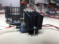
TDA8932 plus Heatsink
Got two of these nice amp board same as OP.
I've run both trough their paces : 24V DC supply , 8Ohm Load , Sinus stimulus.
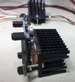
No big deal here they perform as advertised; pending more accurate test, that i will post on the forum as soon they are completed, I left them idling with no signal input , after an our or so i did find them too hot, so I decided to put an heatsink on them . Included are the pictures of my hack to put an heatsink on the board that is not really meant to have one.
The heatsinks are from old cpu coolers and a small copper block, cut at dimension, is used to ensure good thermal contact plus enough elevation not to touch the capacitors near the chip.
The finned part is screwed to a metal bridge tab insulated trough a small plastic insert that keeps everything together.
TEST : after an our at 25.4 V supply @Tamb 26.5c , Theatsink is 35.5c.
not bad from too hot to good .
Got two of these nice amp board same as OP.
I've run both trough their paces : 24V DC supply , 8Ohm Load , Sinus stimulus.
No big deal here they perform as advertised; pending more accurate test, that i will post on the forum as soon they are completed, I left them idling with no signal input , after an our or so i did find them too hot, so I decided to put an heatsink on them . Included are the pictures of my hack to put an heatsink on the board that is not really meant to have one.
The heatsinks are from old cpu coolers and a small copper block, cut at dimension, is used to ensure good thermal contact plus enough elevation not to touch the capacitors near the chip.
The finned part is screwed to a metal bridge tab insulated trough a small plastic insert that keeps everything together.
TEST : after an our at 25.4 V supply @Tamb 26.5c , Theatsink is 35.5c.
not bad from too hot to good .
Attachments

I know this is inefficient, but even class D amps love clean power. Tda8932 is not that efficient looking the heat is dissipating. Allo implemented something like this on their tpa3116 amp and getting very good results. https://allo.com/sparky/volt-plus-amp.html
I have a tda7297 which uses very low current with the same cap multiplier onboard and the sound quality is excellent.
Sent from my ONE A2001 using Tapatalk
I have a tda7297 which uses very low current with the same cap multiplier onboard and the sound quality is excellent.
Sent from my ONE A2001 using Tapatalk
TDA 8932bt Test
Hi all
In the end I managed to do some testing of the board today and here are the results.
Test Parameters
Power supply @ 25,4VDC stabilised
Load @ 8 Ohm
Pout @ 1 W
Tamb @ 26°C
about the graphs
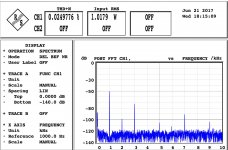
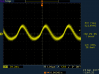
Residual is a snapshot of the output without input it shows that the internal pwm oscillator runs at 522 kHz well above the audibility human threshold and also above the tweeter possibilities.
THD is pretty clear, it's total harmonic + noise @1kHz @1W plus a graph of the spectrum of the firsts 10 harmonics
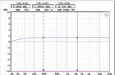
freqresp is simply a graph of the frequency response @1W 20Hz-20kHz.
it shows that there is a small loss at lower than 100Hz but nothing really dramatic, just don't use the amp to drive a super-duper subwoofer as it probably is not so great below 20Hz
While I will not call them Hi-Fi, they are nonetheless, for the price they cost, not bad.
Pending more tests will post here when ready.
Hi all
In the end I managed to do some testing of the board today and here are the results.
Test Parameters
Power supply @ 25,4VDC stabilised
Load @ 8 Ohm
Pout @ 1 W
Tamb @ 26°C
about the graphs
Residual is a snapshot of the output without input it shows that the internal pwm oscillator runs at 522 kHz well above the audibility human threshold and also above the tweeter possibilities.
THD is pretty clear, it's total harmonic + noise @1kHz @1W plus a graph of the spectrum of the firsts 10 harmonics
freqresp is simply a graph of the frequency response @1W 20Hz-20kHz.
it shows that there is a small loss at lower than 100Hz but nothing really dramatic, just don't use the amp to drive a super-duper subwoofer as it probably is not so great below 20Hz
While I will not call them Hi-Fi, they are nonetheless, for the price they cost, not bad.
Pending more tests will post here when ready.
Attachments
http://www.diyaudio.com/forums/class-d/87913-class-d-amp-photo-gallery-128.html#post5127032
Here are some pictures of my TDA8932 amplifier
Here are some pictures of my TDA8932 amplifier
Have you done more tests yet? These ones were really interesting. Did you have a heatsink on the chip?Hi all
In the end I managed to do some testing of the board today and here are the results.
Test Parameters
Power supply @ 25,4VDC stabilised
Load @ 8 Ohm
Pout @ 1 W
Tamb @ 26°C
about the graphs
Residual is a snapshot of the output without input it shows that the internal pwm oscillator runs at 522 kHz well above the audibility human threshold and also above the tweeter possibilities.
THD is pretty clear, it's total harmonic + noise @1kHz @1W plus a graph of the spectrum of the firsts 10 harmonics
freqresp is simply a graph of the frequency response @1W 20Hz-20kHz.
it shows that there is a small loss at lower than 100Hz but nothing really dramatic, just don't use the amp to drive a super-duper subwoofer as it probably is not so great below 20Hz
While I will not call them Hi-Fi, they are nonetheless, for the price they cost, not bad.
Pending more tests will post here when ready.
Allo did a great job with TDA3116D2 but maybe not only with the cap multiplier but the 4 layer PCB also.
In tests it was not significant better than a "cheap" chinese board (For the tests i ran like 1kHz THD vs. Pout for different loads). The main advantage comes from the better inductors used.
Last edited:
I went through a whole range of options, starting out with 10uF ceramic I think and then up to a few thousand uF in low-ESR caps. Eventually I settled on a discrete regulator and it turns out you can get away with a lower voltage than the main supply when running (as I was doing) at 24V and above for the output stage.
I did change the 10R resistor yes, reduced it to 3.3ohm when I went to electrolytics, then also tried an inductor instead of it. The inductor sounded cleaner than the resistor.
This is very interesting to read. I have been going crazing trying everything imaginable to get rid of the fuzz that rides on clean, pure sounds at low levels, particularly on solo piano or solo voice. I have been running my TDA8950 amp in stereo, SE mode with main supplies of +/-30VDC. I have added the missing coupling cap on the VSSD pin, tried adding additional decoupling, etc. My layout is very similar to that of an earlier NXP evaluation board. Just today I found that if I lower my supply voltage to +/-25VDC the fuzz distortion is almost completely inaudible. Thinking along the same lines as you, I was wondering about running the analog stages (VDDA, VSSA) at a lower voltage than the output stage. With your implementation, how low were you able to go with the analog stage voltages? I am thinking of trying a simple resistor plus zener initially to set the analog stage voltages to +/-20VDC or possibly even lower, leaving the output stage at +/-30VDC. Maybe this is the way to finally cure the cursed fuzz?!
This is very interesting to read. I have been going crazing trying everything imaginable to get rid of the fuzz that rides on clean, pure sounds at low levels, particularly on solo piano or solo voice. I have been running my TDA8950 amp in stereo, SE mode with main supplies of +/-30VDC.
Probably worth pointing out that my comments were made about the TDA8932, not the 8950. They're quite different beasts - not least because of the latter using balanced rails.
I have added the missing coupling cap on the VSSD pin, tried adding additional decoupling, etc. My layout is very similar to that of an earlier NXP evaluation board. Just today I found that if I lower my supply voltage to +/-25VDC the fuzz distortion is almost completely inaudible.
I have had similar 'fuzz' distortion on my TDA8932s which I fixed by adding small value (about 470R) damping resistors right at the (4) input pins of the chip and then isolating the input with a custom-made ferrite cored transformer built on an EP19 core-set. I figured that the fuzziness was caused by high frequencies feeding back from the switching outputs to the inputs and the input stage demodulating the RF into audio. Input wires to the chip act as sufficiently efficient antennas to couple noise in but the input resistors help to soak this up. The transformer makes the effective input wire length much shorter through giving a high degree of CM rejection.
Thinking along the same lines as you, I was wondering about running the analog stages (VDDA, VSSA) at a lower voltage than the output stage. With your implementation, how low were you able to go with the analog stage voltages?
With the 8932, I settled for around 13 to 14V. I found lower (12V say) worked most of the time but occasionally there would be some strange distortion evident. Cleaning up the analog supplies vastly (and I do mean vastly, the improvement is substantial) improves the HF purity from this chip, making it a real high-end contender.
Tolerance to voltage includes the datasheet figures; however, that can vary by sample, as to whether the board's components had the tolerance.With the 8932, I settled for around 13 to 14V. I found lower (12V say) worked most of the time but occasionally there would be some strange distortion evident. Cleaning up the analog supplies vastly (and I do mean vastly, the improvement is substantial) improves the HF purity from this chip, making it a real high-end contender.
I applied your mods, except muntzed a lot, to TDA8932, and got it stable for 88 watts to 9.1 ohms. Sure, that was in a thermoinsulator down in a litre of crushed ice. Trouser flapping concert-authentic audio from a half business card sized board was fun!
So, the higher voltage isn't useful unless there's a way to cool the chip for it. However, the audio quality doesn't necessarily go down at higher voltage because it was already overcomp and making it a bit more nervous (less overcomp) increases the audio quality. Surely there's a less-daft way to do it than what I tried. Possibly Pin#12?
I applied your mods, except muntzed a lot, to TDA8932, and got it stable for 88 watts to 9.1 ohms. Sure, that was in a thermoinsulator down in a litre of crushed ice. Trouser flapping concert-authentic audio from a half business card sized board was fun!
The aims of my mods are improving the SQ not delivering more output power. I run the output stage at the highest voltage so as to allow the highest load impedance - my usual output power target is 15-20W. Running the analog stages below half the voltage applied to the output stages keeps the chip cooler as the quiescent current (40mA) is substantial.
Me too. Except when checking out the chip's onboard limiter. It is apparently sensitive to loading and temperature, mainly temperature.. . . my usual output power target is 15-20W. Running the analog stages below half the voltage applied to the output stages keeps the chip cooler as the quiescent current (40mA) is substantial.
I also checked 4 ohms, higher voltage, SE mode compared with 8 ohms, lower voltage bridge mode. Even at approximately similar wattage output, the temp is much cooler in SE mode (when only one of the chip's amplifiers is in use).
- Home
- Amplifiers
- Class D
- Fasten seat belts. TDA8932 pessimistic review.