As for your alternate Ultra woofer question...
The Fane, as you note is WAY more efficient. It would require a substantial rework of the crossover and the limited efficiency of the Vifa would not allow you to take advantage of the Fane's efficiency. There are also woofer Q issues too. If you happened to have a pair of the Fanes to play with, it would be interesting to experiment.
Sorry John. In the back of my mind I thought the Vifa was more efficient. Oops!
Manzi amp compatibility
mnsouthpaw, thanks for your report back on your OTL and other amplifiers working well with the Manzi. No Manzi amp issues so far other than having adequate power for the listeners preference.
As for your proposed rounded baffle edge mods, if you do experiment, would love to get your opinion and learn more about what you try.
Thank you for your positive comments as to simplicity and design.
As for exposing more people to a low cost, simple high fidelity speaker, that WAS the motivating factor for this project thread.
Thanks again to Pano for putting it all together so well!!
Hopefully as more Manzi's are built there will be enough of them to reach a critical "mass" if you will and a lot more music lovers will be exposed to and enjoy what a simple, musical speaker can do.
I continue to experiment with lower cost, off the shelf amps for the Manzi.
Dusting off my old ASL EL84 based P-P, 30 WPC class A. Try it in stock condition. Haven't listen to the current Vifa version of the Manzi with the ASL. Was pretty good with the original Seas tweeter version.
Then see what upgrading the low level 12AU7's with NOS US manufacture tubes does. Maybe add a choke to the power supply. See how that combo sounds.
Seems any reasonable quality 30 WPC (at 8 ohms) is adequate for most listening situations. For those on a tight budget the PE Dayton DTA-1 at $90 is a great place to start.
For a few hundred bucks you can buy a decent CD player, build a pair of Manzi's and have enough power with the DTA-1 to make it all work.
Parts are ordered. I kicked this around for over a year but decided to try the OB route because it would be new. Have the 3/4" baltic birch on hand as well. Thanks to John, Pano and others for your contributions to this thread.
Will provide updates as I build and test.
moto
Will provide updates as I build and test.
moto
John, I'll be sure to check in with what I learn along the way. Updates will be somewhat spread out since I'm also fooling around with an infinite baffle set up.
.....Not enough time for all the fun.......
Good luck Moto! this was my first speaker building project...not sure if you've done this before, if not, great way to start. If others are sitting on the sidelines.... go for it!
.....Not enough time for all the fun.......
Good luck Moto! this was my first speaker building project...not sure if you've done this before, if not, great way to start. If others are sitting on the sidelines.... go for it!
In another thread Pano wrote:

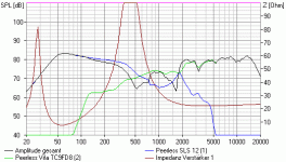
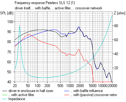
We see a big hole in the frequency response around the crossover frequency. Same as already shown by Erling in his MJK worksheet.
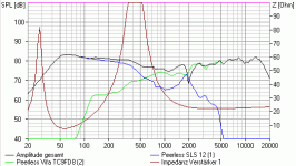
By connecting woofer and fullrange in same polarity, the FR diagram looks a lot better:

The passive crossover network pushes low frequencies for the woofer.
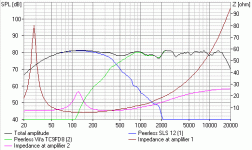
Lets compare that to an active crossover solution with a 6 dB/oct LP at 40 Hz and a 24 dB LP at 1220 Hz for the woofer:

There is no longer a 20 mH inductor, which has to work against the rising inpedance of the woofer at resonance. As a consequence the response rolls off early.
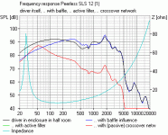
The last diagram shows how the coil pushes the SPL above the limit set by the baffle. Below the resonance peak SPL falls below the baffle influence again:

A 6-7 dB bandpass filter at 50 Hz should help the DCX to arrive at the same FR as the passive version.
I looked into that for the Manzanita with some Boxsim simulations, starting with the passive Manzanita:FWIW, I found it very difficult to get good results on OB using the DCX. Maybe I just didn't understand what I was doing - OB crossovers are strange - but using a big coil on the woofer always gave better results. For more normal box speakers, it was much easier.
We see a big hole in the frequency response around the crossover frequency. Same as already shown by Erling in his MJK worksheet.
By connecting woofer and fullrange in same polarity, the FR diagram looks a lot better:
The passive crossover network pushes low frequencies for the woofer.
Lets compare that to an active crossover solution with a 6 dB/oct LP at 40 Hz and a 24 dB LP at 1220 Hz for the woofer:
There is no longer a 20 mH inductor, which has to work against the rising inpedance of the woofer at resonance. As a consequence the response rolls off early.
The last diagram shows how the coil pushes the SPL above the limit set by the baffle. Below the resonance peak SPL falls below the baffle influence again:
A 6-7 dB bandpass filter at 50 Hz should help the DCX to arrive at the same FR as the passive version.
Sorry. When wrtiting my posting, I got into the forum "Maintenance". Must have been bad for the attachments. Here we go again ...
In another thread Pano wrote:
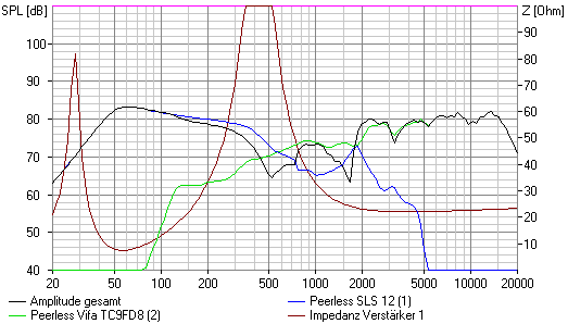
We see a big hole in the frequency response around the crossover frequency. Same as already shown by Erling in his MJK worksheet.
By connecting woofer and fullrange in same polarity, the FR diagram looks a lot better:
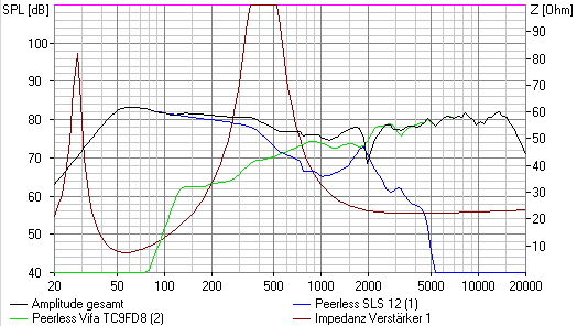
The passive crossover network pushes low frequencies for the woofer.
Lets compare that to an active crossover solution with a 6 dB/oct LP at 40 Hz and a 24 dB LP at 1220 Hz for the woofer:
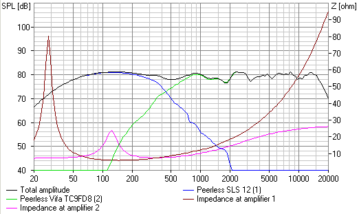
There is no longer a 20 mH inductor, which has to work against the rising inpedance of the woofer at resonance. As a consequence the response rolls off early.
The last diagram shows how the coil pushes the SPL above the limit set by the baffle. Below the resonance peak SPL falls below the baffle influence again:
A 4-5 dB bandpass filter at 50 Hz should help the DCX to arrive at the same FR as the passive version.
In another thread Pano wrote:
I looked into that for the Manzanita with some Boxsim simulations, starting with the passive Manzanita:FWIW, I found it very difficult to get good results on OB using the DCX. Maybe I just didn't understand what I was doing - OB crossovers are strange - but using a big coil on the woofer always gave better results. For more normal box speakers, it was much easier.
We see a big hole in the frequency response around the crossover frequency. Same as already shown by Erling in his MJK worksheet.
By connecting woofer and fullrange in same polarity, the FR diagram looks a lot better:
The passive crossover network pushes low frequencies for the woofer.
Lets compare that to an active crossover solution with a 6 dB/oct LP at 40 Hz and a 24 dB LP at 1220 Hz for the woofer:
There is no longer a 20 mH inductor, which has to work against the rising inpedance of the woofer at resonance. As a consequence the response rolls off early.
The last diagram shows how the coil pushes the SPL above the limit set by the baffle. Below the resonance peak SPL falls below the baffle influence again:
A 4-5 dB bandpass filter at 50 Hz should help the DCX to arrive at the same FR as the passive version.
Attachments
A bit more on Manzanita design considerations
Rudolf
Thanks for running and sharing the simulations... always interesting to see.
A couple of comments. As for woofer - mid-tweet polarity. I am currently running my set of Manzi's in phase. However, you can run them in reverse polarity with subtle audible differences. Normally with a mono-pole, the reverse polarity would be easy to hear in the crossover region, as in a suck out (a deep one at that) . For the Manzanita OB, rear wall distances and listener preferences determine which polarity sounds better for each listener. One of the little niceties of the Manzanita, you can easily adjust polarity to suit your personal preferences. The reverse phase is slightly more relaxed but with greater sound stage depth and width. Positive polarity is a bit more forward with tighter imaging. If your rear wall is highly reflective, the reverse phase seems to be the better of the two.
The real beauty of th design is that we get a flat summation with only a hand full of "off the shelf" crossover components.
So what's going on the sims are not picking up on? It's the rear radiation and each drivers unique cancellation - peaking slopes created by Open Baffle and other mechanical effects. The rear radiation consists of a pair of humps, a lower frequency one from the Peerless and the broader hump higher up from the Vifa. The F = and F peak values for each driver are intentionally different, based on their respective positions on the baffle. The driver positions I have selected try to make best use of rear radiation realities, plus provide forward baffle diffraction smoothing. This smoothing really helps improve the forward power response.
Basically the OB "F" values reflect (no pun intended) shortest distance from each driver's center to the closest baffle edge. This is where OB, especially a relatively small OB is tricky. And to make things even more complicated, the shape of the humps are very different for the woofer and the mid-tweet. These "hump" shape differences are a combination of F= and F peak values plus the how the rear magnet assemblies create ripples and higher frequency roll off(s) not present in the forward radiation patterns.
Keep in mind, rear radiation at the center of the humps can be as much as 6 db! In actuality, 3-4 db is typical in the listening chair in certain parts of the spectrum.
If you measure the Manzinita with a positive polarity in a typical room with the Manzanita baffle face at a distance of 24"-50" from the rear wall, the output measured at a 8-14' listening distance for a seated listener is FLAT, and I mean FLAT! In reverse phase there is a broad, shallow dip (2-3 db) in the lower mid range. The only exception is a narrow 50 Hz or so peak (2-6 db depending on rear - side wall set up distance(s) and room size). Polarity has no effect on the 50 Hz peak.
The real beauty of the design is we get a flat summation with only a handfull of "off the shelf" crossover components.
Very kind of you, John
to share even more of your design considerations for the Manzanita.
My comparison of the polarity sims was just out of curiousity (since it was just a push of a button). Boxsim simulates in "free air" without any boundary influences. Listening distance is infinite and rear radiation is expected to be the same as to the front. You have already explained how exchanging all of this with real world data makes a difference.
It wasn't without some hidden agenda that I wrote "By connecting woofer and fullrange in same polarity, the FR diagram LOOKS a lot better" - and not "WORKS a lot better".
Two SLS 12 are sitting on the shelve here collecting dust, and I own a DCX. The little FR drivers don't cost that much, but sadly I don't own a copper mine at the moment. So I was curious how an active Manzanita would fare. After your explanations I shouldn't rely on a nice flat direct response simulation (which was quite easy to achieve) to do the trick.
Rudolf
to share even more of your design considerations for the Manzanita.
My comparison of the polarity sims was just out of curiousity (since it was just a push of a button). Boxsim simulates in "free air" without any boundary influences. Listening distance is infinite and rear radiation is expected to be the same as to the front. You have already explained how exchanging all of this with real world data makes a difference.
It wasn't without some hidden agenda that I wrote "By connecting woofer and fullrange in same polarity, the FR diagram LOOKS a lot better" - and not "WORKS a lot better".
Two SLS 12 are sitting on the shelve here collecting dust, and I own a DCX. The little FR drivers don't cost that much, but sadly I don't own a copper mine at the moment.
Rudolf
Ditto Rudolf,
I have two sub amps with DSP, equalizer, second or third order filtering up to 350hz and possibility to connect measuring with DSP. Also four SLS is present + one Sonido 178 wide band driver. What to do next
Well, obviously start to do something, hopefully after easter......
Nice thread BTW )
)
Peter
I have two sub amps with DSP, equalizer, second or third order filtering up to 350hz and possibility to connect measuring with DSP. Also four SLS is present + one Sonido 178 wide band driver. What to do next
Well, obviously start to do something, hopefully after easter......
Nice thread BTW
Peter
Active Manzanita
Hi Pano and John and well all!
I just got the SLS12s and will start the build this week. Unfortunately I don’t have the same tweeter so I will use an SS D2905/9500 from another project instead. I will use my miniDSP as crossover. So what would my initial set up be? Close to the passive crossover from the start of this thread? Is there anyone who have done it and could offer some advice?
Dag
SS D2905 info
Hello Dawa
Thank you for your interest in the Manzanita.
Don't think the D2905 can safely play flat to about 1,500 Hz, which is where you need to be with a second order slope. Passively (2nd order electrical, 3rd order acoustic) 2,000 Hz or so is about it for the 2905.
Second order electrical slopes provide the greatest protection for most dome tweeters. And, you will need to trap the 2905's resonance even at 2,000 Hz second order. It would be a shame to tear up $ 300.00 worth of excellent tweeters. If there is anyway you get get the Vifa TC9FD18-08 I would highly recommend doing that. Way better suited and typically $9.00 - $14.00 each here in the US. Slightly more in Europe.
The one thing about the original design is the Seas TDFC, with a second order it would play down to 1,500 HZ and it was $28.00 then. So if you did tear it up, replacing it was not so bad. And the TDFC has a very low magnitude resonance, so a resonance trap was not required. It was what I happened to have to experiment with when I first worked out the Manzanita design. The TDFC proved to be marginal at best. Why I replaced it with the much larger 1.5" D3806. Escalating D3806 cost and a search for even better lower midrange performance is what prompted the switch to the Vifa TC9.
From my simulation 100 Hz would be the upper limit. 50 Hz 6dB looks better. In both cases you should add a bandpass at 50 Hz which raises the response about 3-6 dB.Ok like 100Hz 6dB?
Anny eq?
All above is rigmarole because we are talking in the middle of room mode land ...
Cheers
Rudolf
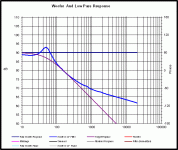
50Hz 1st order is close. Because of the woofer's impedance it really isn't a classic slope of any kind. Below you will see the actual filter function in blue and an ideal 1st order LP @50Hz in purple.
Don't know if you can replicate that with the miniDSP, but I've also attached the filter in text file in case you can use it.
NOTE: What you see below is not the acoustic response, it's the electrical response of that big 20mH inductor in series with the Peerless 12"
Don't know if you can replicate that with the miniDSP, but I've also attached the filter in text file in case you can use it.
NOTE: What you see below is not the acoustic response, it's the electrical response of that big 20mH inductor in series with the Peerless 12"
Attachments
OK so if I understand this correctly the text file could plot a frequency response in Excel and then I will try to mimic this in the miniDSP?
As I understand it the response plot in the miniDSP is actually the electrical output from the filter? And then you measure the actual response plot, the blue line in your graph, yes?
As I understand it the response plot in the miniDSP is actually the electrical output from the filter? And then you measure the actual response plot, the blue line in your graph, yes?
Basically, yes. The blues line is the electrical response. If you can get the response out of the miniDSP, that's great. Don't know if you can. The text files is simply the blue line as frequency, amplitude and phase. You may not need the phase column for the miniDSP.
I don't know if you can load curves like this into the miniDSP, you may have to match the curve by hand. Start with a 1st order Low Pass @ 50Hz and work from there.
You should also try about 0.5 ohms in series with the woofer to mimic the DCR of the big inductor. It may help, or it may hurt, you can let us know.
- Home
- Loudspeakers
- Multi-Way
- Fast, fun, Inexpensive OB project
