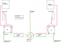
I'm not sure I can actually wind the OT primary wires for both OT's.. I can only place the 3rd capacitor near one of the 845s. The other 845 is going to have to have a length of wire carrying B+ from that 3rd filter cap to the output transformer, and a section of that will be unwound. I could probably change to using a split rail PS type design at that last node, so that one filter cap is located near each 845. I do have another suitable choke and capacitor.
Two caps will improve the amplifier, but even with one C3, we can greatly reduce the loop area.
It needs a picture though, rather than a thousand words - so here we go.
I hope it is self-explanatory. Having the OT primary wiring running parallel gets the output loop under control, and the close running of the driver signal/ground, and elimination of any loop between grid resistor & ground (as shown) will deal with the input loop.
Make sure the Trafo and choke frames & end-bells are grounded (wired back to C3).
Lastly, parallel run the HV rectifiers anode cables.
These are the most pressing problems. Implement these, and you will see a reduction in buzz, I am confident.
Attachments
....but it works just as he states. Stop badgering him and move on. Rod has provided immense contribution to this forum; he deserves more respect than you give him.
Thank you, Kurt!
I am pleased if my effort has been useful in any way.
Two caps will improve the amplifier, but even with one C3, we can greatly reduce the loop area.
It needs a picture though, rather than a thousand words - so here we go.
I hope it is self-explanatory. Having the OT primary wiring running parallel gets the output loop under control, and the close running of the driver signal/ground, and elimination of any loop between grid resistor & ground (as shown) will deal with the input loop.
Make sure the Trafo and choke frames & end-bells are grounded (wired back to C3).
Lastly, parallel run the HV rectifiers anode cables.
These are the most pressing problems. Implement these, and you will see a reduction in buzz, I am confident.
Thanks for the layout, I can definitely rework the layout like this fairly easily.
As for grounding frames and end-bells, are you talking on every transformer and choke? Including power transformer?
Also, if there's no bare metal (like the Edcor OT's, and the Hammond transformers) should I be scraping a section of the finish off the transformers somewhere? And just thinking about this further, I probably shouldn't just scrape it off of one of the mounting points because that would end up grounding at that point on the chassis and creating a ground loop if I'm also running a ground wire back to C3.
Yes, most seriously, every one.
Attaching a wire to a crimped loop-tag and using a screw to attach it to a mounting hole is fine.
Most folks mount chokes and trafos to the chassis, and get away with it just fine. Others mount on 3 insulated washers, and one metal one (to prevent loop around the trafo) - though I have never needed to resort to that.
When you have a chassis, wire it to C3, and ground the end-bells through the chassis - it should be fine like this.
Don't use the chassis to carry signal current, though.
I guess if one of the feet of the transformer is grounded to the chassis, that is still ground, as the chassis will be earth grounded.
I think there is quite a finish on the mounting feet of most of my transformers though, so probably just scrape that off of one of the feet?
When you have a chassis, wire it to C3, and ground the end-bells through the chassis - it should be fine like this.
Don't use the chassis to carry signal current, though.
Apologies.. It's one of those days.. I'm just not quite getting this.. "Wire it to C3, but ground the end-bells through the chassis" ?
I don't quite follow. Are you saying that the end bells and frame are grounded separately? I had assumed that there is a connection between endbells and frame, and that (when in chassis) just having one of the mounting feet in contact with the chassis would provide adequate shielding.
When it's on the prototype board, I'll ground that foot with a ground loop tag back to C3.
"Frame" is just the U-shaped clamp on the chokes (or similar-looking trafos).
"End-Bells" are the two covers on trafos like the Hammond 724.
In each case, just a single connexion to a mounting hole should suffice, so only one wire per trafo or choke. The two end-bells of the 724 should already be connected by the bolts - but no harm to check..
"End-Bells" are the two covers on trafos like the Hammond 724.
In each case, just a single connexion to a mounting hole should suffice, so only one wire per trafo or choke. The two end-bells of the 724 should already be connected by the bolts - but no harm to check..
hum & buzz
Guy’s quit chasing your tails.
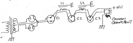
You need to understand CHARGING & DISCHARGING CURRENTS.
Magnetic fields: Power transformer vs. the chokes. Typ are rotated by 90 degrees to minimize the coupling.
Case grounding is usually not a large problem, check the leakage currents. And ground them to the frame. The frame and common ground meet at one place.
Good hunting
Duke
Guy’s quit chasing your tails.
You need to understand CHARGING & DISCHARGING CURRENTS.
- Charge the caps @ the terminals.
- Discharge the caps @ the terminals.
- Don’t use multi caps in common case, as they may have a common ground problem.
- After the last integrator cap this is a common ground point.
- Keep the charging & discharging loop area to a min. Twist or keep the leads short and close to each other.
Magnetic fields: Power transformer vs. the chokes. Typ are rotated by 90 degrees to minimize the coupling.
Case grounding is usually not a large problem, check the leakage currents. And ground them to the frame. The frame and common ground meet at one place.
Good hunting
Duke
Attachments
Guy’s quit chasing your tails.
You need to understand CHARGING & DISCHARGING CURRENTS.
- Charge the caps @ the terminals.
- Discharge the caps @ the terminals.
- Don’t use multi caps in common case, as they may have a common ground problem.
- After the last integrator cap this is a common ground point.
- Keep the charging & discharging loop area to a min. Twist or keep the leads short and close to each other.
Magnetic fields: Power transformer vs. the chokes. Typ are rotated by 90 degrees to minimize the coupling.
Case grounding is usually not a large problem, check the leakage currents. And ground them to the frame. The frame and common ground meet at one place.
Good hunting
Duke
Alrighty, I'm not using any multi caps.
And actually my grounding scheme is almost exactly like you've shown. My common ground point is off of C3. The only difference to your drawing is that I'm earth grounding at C1.. Do you think it's preferrable to earth ground at C3? For some reason it seems like I would want that earth ground farther back in the string..
As for transformer locations, I think you can see in my screenshots earlier in the thread that I do indeed have my chokes 90 degrees offset to my power transformer.
Thanks for the suggestions!
Alrighty, I'm not using any multi caps.
And actually my grounding scheme is almost exactly like you've shown.
And AudioMan's diagram is exactly how it should be done. Including where he shows the system earth right at the right hand side of the diagram. His method ensures that the ripple current in C1 only circulates locally in the diodes and transformer, and cannot produce a voltage drop in any wiring outside the loop.
Ditto with the smaller hum current flowing in the second loop comprising C1, L1, and C2.
However, you should bear in mind that getting this sort of thing wrong typically causes a HUM - a low frequency sound heard in the woofers. It is a conduction coupling problem.
You reported a BUZZ - a high frequency sound heard in the tweeters. That indicates a radiated coupling problem, arising in an internal or external source.
Rod's concept of running go and return wires close together and even twisted together is sound and will address radiation issues. So if it's easy to do, do it. Including for the unregulated inputs to his regulators.
I suspect there is more than one problem though. And if the tubes are oscillating, the amplifier will never be any good - it will distort as well as buzz.
Usually a star washer between transformer metal and the chassis or earth stage at any convenient bolt hole is enough to cut thru paint. But if you have to scrape some paint off, do so.
The insulating washers seen under transformers and chokes in commerical equipment is not there to prevent an electrical earth loop. They are there to space the transformer magnetically off the steel chassis and prevent magnetic flux in the chassis, which can cause a slight noise. It's also good practice to use a nut to tighten up the mounting bolts before attaching a transformer or choke to the chassis. Then a second nut under the chassis.
Incidentally, the pressed metal shells used to enclose some types of transformers are called "cheeks" in the transformer industry. I've never heard them called "bells" before (they shouldn't ring!), and I worked several years as the design engineer in a transformer factory. And purchased/ordered the same in various jobs.
Last edited:
Rod's concept of running go and return wires close together and even twisted together is sound and will address radiation issues. So if it's easy to do, do it. Including for the unregulated inputs to his regulators.
I forgot to point out that if the tube is oscillating, running the anode/output transformer go and return wires togther cannot be relied upon to stop the tube oscillating. It may do. It also may even make oscillation worse.
Incidentally, the pressed metal shells used to enclose some types of transformers are called "cheeks" in the transformer industry. I've never heard them called "bells" before (they shouldn't ring!), and I worked several years as the design engineer in a transformer factory. And purchased/ordered the same in various jobs.
"Cheeks" must be terminology local to you in Australia, it's not used in the Industry here in the UK.
UK makers call them Bells, including Danbury, and the splendid Audio Transformer firm of Sowter, who say "Shroud Bells":
SOWTER TRANSFORMERS DIMENSIONS
In the U.S., Edcor also call them End Bells:
https://edcorusa.com/end-bells
and MercuryMagnetics say the same:
Mercury Magnetics - transformer mounting
I don't know of any current European or U.S. makers calling them "cheeks".
To test the amp with a battery powered filament in one of the 845's, I picked up 8 D Cell batteries, as was suggested earlier in the thread.. I wired up 7 of them in series, which measured 11.2V with no load.. With the load of the 845 filament though, it dropped to 7.5V! lol
I wired an 8th D cell in series, and under load still only measuring 8.5V and dropping rapidly..
I think to test the filament on the 845 with a battery supply, I'll have to just try using a car battery with dropping resistor..
I wired an 8th D cell in series, and under load still only measuring 8.5V and dropping rapidly..
I think to test the filament on the 845 with a battery supply, I'll have to just try using a car battery with dropping resistor..
I take it that you have grounded all transformers and chokes. And that it did not work?
Yes, this takes little time to do, and will get you further than messing around with batteries. Please try it!
To test the amp with a battery powered filament in one of the 845's, I picked up 8 D Cell batteries, as was suggested earlier in the thread.. I wired up 7 of them in series, which measured 11.2V with no load.. With the load of the 845 filament though, it dropped to 7.5V! lol
I wired an 8th D cell in series, and under load still only measuring 8.5V and dropping rapidly..
I think to test the filament on the 845 with a battery supply, I'll have to just try using a car battery with dropping resistor..
No surprise with the consumer D cells - 3.25A is a bridge too far for them.
Even if you stacked up ten of them the voltage would drop another 2V or more in the first couple of minutes - altering the tube characteristics drastically, and undermining your test, as well as running the filament way out of specification.
In any case, even if the buzz reduces with battery-powered filaments, you still have to determine whether it is due to excessive emissions of the raw dc supply or excessive susceptibility of the signal circuit. And since it only takes a glance to see that there will be excessive susceptibility, caused by large loops around the anode & grid circuits.
Circuit-wise the filament raw dc supply you are using is as good as any used by large numbers of Transmitter-amp Constructors all around the World who use my Regulator - without any trouble from buzz. I would prefer to see the iron located somewhat further from the signal parts, admittedly - but the only test for that is simply to try moving it.
The regulator is measuring normally, so there is little chance of conducted noise ingress.
Therefore, my suggestion is to fix the susceptibility problem first. This is a definite problem which can be seen to exist - just by looking.
Moving C3 and wiring as I have suggested in my diagram above should not take long to do - and you will have to do it anyway, I am confident of that.
Attachments
To test the amp with a battery powered filament in one of the 845's, I picked up 8 D Cell batteries, as was suggested earlier in the thread.. I wired up 7 of them in series, which measured 11.2V with no load.. With the load of the 845 filament though, it dropped to 7.5V! lol
I wired an 8th D cell in series, and under load still only measuring 8.5V and dropping rapidly..
I think to test the filament on the 845 with a battery supply, I'll have to just try using a car battery with dropping resistor..
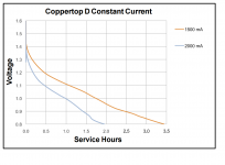
I'm sorry I induced you to buy D cells and you found they were not up to it.
I did in fact check discharge curves and verified 7 cells should be able to maintain over 9 V for 10 minutes or so, and you only need 1 minute to hear the difference. But I forgot the tube starting (cold) current, which will be about 16 A, and would have polarised the cells.
Only 9V permanently applied is definitly not the way to get full performance and a long life out of the tubes, but certainly would be sufficeint for a quick noise diagnostic test.
The battery test is definitely worth doing though, even if the probability of the filament power supply (diode hash, regulator fault, or whatever) being the cause of the noise is not that high. One way or another, it will definitely rule in or rule out the filament power supply as the problem, and give you confidence about it.
You would have success warming up a tube of the AC supply and then changing over to battery with a wired-in switch, or by using 14 D cells wired in two parallel strings of 7 cells, but I guess you've had enough of buying and flattening D cells.
Last edited:
To demonstrate what can be done with properly implemented dc regulated heating of high-power transmitters - especially if you're looking for a model layout of the filament AND HV raw dc supplies, check out Magz's "MidLife Crisis" here on DIYaudio.
The 833C has a 10.0V 10A filament. For each filament, the MidLife Crisis uses a parallel pair of Coleman regulators, and an LCLC raw supply using Hammond 159ZLs and Panasonic TSHA capacitors (for high ripple-current durability).
The anode supply is 2.5kV.
The thread is well-worth a read for any contructors of high-power Transmitter Tube amplifiers.
Layout of the raw dc:
http://www.diyaudio.com/forums/tube...e-crisis-my-833c-amp-build-9.html#post3671833
The MidLife Crisis uses a separate sub-chassis for the power supplies - making it much more straightforward to avoid nearField-coupled noise.
Note how each supply uses short, direct, twisted pairs of wires to hook up. This is the model to follow!
Check the picture to see how it's done:
http://www.diyaudio.com/forums/tube...-crisis-my-833c-amp-build-10.html#post3731406
http://www.diyaudio.com/forums/tube...-crisis-my-833c-amp-build-11.html#post3752143
See also how Magz added some extra screws to the 159 chokes, to reduce mechanical buzz.
And so to the punch-line. Is it quiet?
The output noise into a 4 ohm speaker measured 190microVolt, even with an unregulated HV supply.
We can see the spectrum and set-up here:
http://www.diyaudio.com/forums/tube...-crisis-my-833c-amp-build-12.html#post3778497
My advice:
If you like the sound of the 845-SE, start work on wiring it up correctly, using examples from Magz's work. If you are in doubt, please sketch it out beforehand, and we will advise.
A separate chassis for power supplies is not mandatory - but is does mean that achieving very low noise will be much easier.
But please do not think that your raw dc supply's design or components are responsible for the problem - at worst, only their location is at fault - bar any uncorrected large loops in the wiring (there are no obvious ones).
See how it can be done at 10.0A with almost identical schottky rectifiers to yours - and simply concentrate on layout & wiring. As I have already said - you will have to fix this, if only to eliminate it from enquiries. Fixing these problems will always give a better-sounding, lower noise amp, and you will learn techniques that are useful for evey amp you build.
Getting to work on it now will achieve results that carry through to the final result.
Last edited:
- Status
- This old topic is closed. If you want to reopen this topic, contact a moderator using the "Report Post" button.
- Home
- Amplifiers
- Tubes / Valves
- Faint buzz through power stage (845)