theHoj,
What is the voltage across the 845 filaments?
I know the 845 design centre rating is 10V, but what voltage is it actually getting? I assume you have a multimeter of known good accuracy. At a pinch you could use your CRO with the two inputs set for display in differential mode (ie CRO subtracts one input from the other and displays the difference)
I don't know anything about the regulator requirements, or how it works, but it is possible if the filament voltage is high, the regulator may not have enough headroom to regulate and so may let noise though. A circuit of the regulator or at least the application manual would be nice, but I could not find one on the WWW.
Last edited:
theHoj,
What is the voltage across the 845 filaments?
I know the 845 design centre rating is 10V, but what voltage is it actually getting? I assume you have a multimeter of known good accuracy.
I don't know anything about the regulator requirements, or how it works, but it is possible if the filament voltage is high, the regulator may not have enough headroom to regulate. A circuit of the regulator or at least the application manual would be nice, but I could not find one on the WWW.
Joel has already provided the measurements.
His 15.5V raw dc is more than enough to meet the Regulator's input requirements, for his 10Vdc output.
My Regulator is adjustable, and it is very easy to set 10.0V exactly on an 845.
Joel has already provided the measurements.
His 15.5V raw dc is more than enough to meet the Regulator's input requirements, for his 10Vdc output.
My Regulator is adjustable, and it is very easy to set 10.0V exactly on an 845.
I had assumed it was adjustable, so it can be made to suit whatever tube is in use.
Since it is adjustable, it is possible that the OP set it with the aid of a multimeter that was out of calibration, and it is too high. If only I had a dollar for all the folk I've met who have been misled this way. Or he simply made an error in setting it.
Now, how about answering questions concisely and factually, seeing as you appreciate science?
Exactly how is the noise isolation implemented?
What is the exact specified mininum input voltage (presumably a voltage above the output) the regulator requires?
Last edited:
So you had assumed it was only a single sided regulator?
Both sides are regulated.
Well, there is only one output. How can there be a regulator in each side in a const current regulator? With only one (floating) source and one output, both sides must be in series. So what happens if one regulator, due to tolerances, wants to put out slightly more current than the other?
You better provide a good coherent explanation.
You can send me the manual via private message if you like. A circuit would be better, but I can appreciate you being nervous about that - you have no idea who I am. But I can assure you I won't post it anywhere if you don't want me to. I only want to help the OP.
Now, how about answering questions concisely and factually
....
You better provide a good coherent explanation
I'm not here to submit to your interrogations. You have responded to too many of my contributions to this thread with a monstrous degree of Trolling already.
Joel has been in touch with me privately, before this thread was even launched, and we have discussed all of his measurements, design of the raw dc, and I am satisfied that he has built and implemented it correctly.
I am also satisfied that the nature of the layout of his prototype is responsible for the buzz.
The measures I suggested for rectifying the layout, if we say twisting the rectifier leads, rather than move the rectifiers - must be attended to before any investigation into the filament supply is necessary.
If I should fail to be right about that, Joel may have support from me, the Designer of the Regulator, at any time. Just as all DIYers here know, where my Regulators are concerned.
Which all sounds good, on the face of it.
But you have used this post to make personal attacks instead of providing reasoned technical argument. You started this discussion on regulators. You started with personal attackes long before anything that I said that could be construed personal.
Not one question have you answered, and they are all reasonable questions.
Why have you not answered technical questions? Because they are an unreasonable inteerogation? Or because you can't, without embarrasing yourself?
All that, and this bit of snake oil in your Post #20:-
The filament has a differential signal voltage across it, due to the gm and bias skew brought on by the filament voltage gradient. A voltage regulator - whose feedback is sourced directly across the filament - sees this music signal, and tries to null it out - clumsily, because it's an Ampere-level regulator.
So, your credibility is gone. Re that quote above, you are either snake oiling or you really have no idea how circuits work. One, or the other.
That's classic, Keit doesn't understand how one can regulate both sides in a current regulator. I thought you were the expert, every post you make implies it...
Not only is it easy to understand without having Rod explain it (and I hope Rod doesn't), but it works just as he states. Stop badgering him and move on. Rod has provided immense contribution to this forum; he deserves more respect than you give him.
Not only is it easy to understand without having Rod explain it (and I hope Rod doesn't), but it works just as he states. Stop badgering him and move on. Rod has provided immense contribution to this forum; he deserves more respect than you give him.
Said regulator, or the tube, may be oscillating, but since the OP doesn't have access to an oscilloscope we'll never know. Though one not particularly refined way way to test for oscillation would be with a portable AM radio.
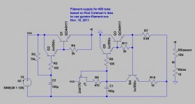
Keit, it's possible Rod's regulator still uses the idea of sandwiching the filament between a CCS and a cap multiplier (or gyrator), such as the attached circuit. I used this particular idea with good results.
Keit, it's possible Rod's regulator still uses the idea of sandwiching the filament between a CCS and a cap multiplier (or gyrator), such as the attached circuit. I used this particular idea with good results.
Attachments

That's classic, Keit doesn't understand how one can regulate both sides in a current regulator. I thought you were the expert, every post you make implies it...
Not only is it easy to understand without having Rod explain it (and I hope Rod doesn't), but it works just as he states. Stop badgering him and move on. Rod has provided immense contribution to this forum; he deserves more respect than you give him.
I did a bit of googling to see if there is any info on the Rod Coleman regulator. Turns out there are photos of the board (at least two versions) but I could not find a circuit. Text on a few websites says that one rail is current regulated, and the other is filtered. But in Rod's post above #82 that both sides are regulated. So there is a discrepancy.
Rod may well have contributed a lot to this forum. But with his post #20 about "clumsy ampere level regulators", and his words on a website (Bartola) I quote here:-
There are [at least] 4 reasons to use athe CCS/gyrator architecture:
- Establish a high dynamic impedance between the Filament terminals. I don’t know if there’s some kind of micro-phasing effect, or something else, but it is certainly important. If you connect this circuit to a DHT and enjoy the wonderful sound for a while, then try putting a 1uF across the filament – the sound is degraded below AC standard.
And Rob provided this gem:-
The gyrator is an open-loop regulator, while the CCS has feedback network which is not in contact with the filament. There’s a big difference.
Well, unless Rod employs a ferritic gyrator (and his circuit board clearly does not - it's way to small for a start), it has to be implemented using active electronics (transistors, FET,s or op-amps) and the only way to do that is to employ negative feedback - which the gyrator terminals see. Check in any textbook on the design and aplication of gyrators eg Huelsman's standard text. Feedback is fundamental to teh operation of electronc gyrators - they are basically two amplifers in a loop, input of one connected to the output of the other, so that whatever impedance is connected across one set of terminals causes a reciprocal impedance seen looking in at the other terminals. 100% neg feedback at the terminals.
Rod could maintain credibility if he showed by technical reasoning why my technical reasin is wrong, and by answering simple questions. But he doesn't - he just makes claims and personal attacks. So he's fair game. He started it.
He's fair game in any case because he's using snake oil words to suck in the gullible.
Last edited:
Said regulator, or the tube, may be oscillating, but since the OP doesn't have access to an oscilloscope we'll never know. Though one not particularly refined way way to test for oscillation would be with a portable AM radio.
The OP does have an oscilloscope, a Philips PM-series. If you read ealier posts, I suggested using it, and decribed how to do it safely. Unfortunately the result was somewhat unclear, as the OP hasn't had much oscilloscope experience and only has a mobile phone to take a picture, but it did suggest the tube is indeed oscillating.
Unfortunately His CRO has only a 10 MHz bandwidth. As the oscillation is probably well up in VHF the oscilloscope gave only a small brief deflection, which could have been radio transmitter pickup (those long leads and no chassis again!). I don't know if the OP is close to a transmitter.
I gave the OP the usual cure - a low Q LC circuit in series with the anode.
I also in an earlier post suggested using a multiband radio to see if any RF could be picked up that dissappeared when the amp was switched off.
Th OP is adamant that shorting the grid resistors to ground completely stops the noise. The noise is heard predominately through the tweeters, not the woofers (3 kHz cross-over). Shielding the grid leak made a minor improvement. Thus it seems likley there are multiple causes, which could be:-
1) Radiated or conductive hash from the filament supply rectifers.
2) Tube oscillating
3) Possibly radiated hash from HT rectifers, since it appears transformer cheeks are unearthed.
4) Radiation from some some external device.
5) Misadjustment of the filament regulator, so it cannot regulate properly.
(5) is probably least likely, and Rod has assured us he has worked with the OP privately to ensure its not the case. However, since Rod will not provide specifcations for the regulator, and has not demonstrated competence (see those quotes and more), the possibility cannot be verified unless the OP comes back and verifies it (eg multimeter used to set the filament current is known good).
Rod is quite correct in pointing out that the wiring routes and layout are not ideal, but it will be a lot of work for the OP to correct this. I have advised him to try easier things first, and reason it out. If ultimately correcting the layout finally fixes it, well and good. No harm done.
Back at the beginning of this discussion, you ignored your best clue. When you grounded the grid, the noise stopped. The grid resistor really is too big. Try 1.5K instead. You could also reduce the 250K to ground as well to 100K and not suffer much loss. It sounded like a ground loop at first - you never showed your layout - "ground" isn't ground all over. Ground that 250K to the same spot as the cathode ground. I see this a lot.
I've tried a variety of grid stopper resistors, I've used no resistor, 1K, 4.7K, and 10K, no noticeable change in buzz. Also the 250K grid leak resistor (249K actually) is there to minimize ac loadline rotation of my driving stage. The driver stage which will feed this power stage has an output impedance of about 12.6K.
I could probably go a bit lower than 250K on the gridleak, and I guess just as a test even I could try a 100K resistor to see what effect that has.
Also, the 249K grid leak resistor is grounded to the exact same location as the cathode ground.
Soemthing else to try, if you have the requirments on hand, before you do a whole lot of work rebuilding:-
While you have used a shottkly bridge rectifier in the filament supply, and effectively a choke input filter, the bridge could still be a source of noise. And because DC feeding provides a straight run from filament -ve, you have another two possible contributors to the buzz.
Try disconnecting the filament current regulator, and temporarily powering the filament in one channel direct from a battery. A battery is a perfect noise free DC source (apart from droop under load and limitted life)
Two possibilities for the battery:-
1) 7 D-size (or C-size at a pinch) 1.5V torch cells connected in series by wires soldered on the ends. I often solder cells up in series when I need a few low noise DC volts to check something. Soldering wires on the ends doesn't appear to hurt them. I solder the wires to the side of centre so that I can still put them in a torch afterwood - or in some vintage battery powered electronic items I have.
2) A "12V" motorcycle or car battery temporarily removed from the vehicle. Since a charged lead acid battery actually puts out about 13.8V on moderate loads, and the 845 filament requires 10V @ 3.25A, you will need a series dropping reistor of (13.8 - 10) / 3.25 = 1.2 ohms. The power dissipated in the resistor will be 12.4 Watts, so use something rated to take it. A 1.2 ohm 10W resistor will be ok for a short test, thoough it will get very HOT! Or two 2.2 ohm 5 watts resistors in parallel. Or three 3.3 ohm 5 watt resistors in parallel.
Keep the filament powering wires as short as possible during the battery test.
Don't forget what I said before: At the very low level of buzz you are reporting, and the results of the tests you reported, there seems to be multiple causes of the buzz. Therefore there may be no single cure.
If you find that powering the filament from a battery reduces the buzz, tell me, and I'll give you a solution or two so you don't need to always have a battery.
I'll try the battery idea, easy enough to see what effect there is.
In my view, the "susceptibility loop" should be corrected first: i.e. the receiving "search-coil" formed by the loop : anode -> OT primary -> -> HV+ -> HVcap -> Ground.
Move Cap-3 and rewire the OT primary in parallel or twisted 5kV cable.
The advantage of doing this first is that is reduces noise caused by ALL non-conductive sources - whether from within the amp, or from some nearby equipment.
I'm not sure I can actually wind the OT primary wires for both OT's.. I can only place the 3rd capacitor near one of the 845s. The other 845 is going to have to have a length of wire carrying B+ from that 3rd filter cap to the output transformer, and a section of that will be unwound. I could probably change to using a split rail PS type design at that last node, so that one filter cap is located near each 845. I do have another suitable choke and capacitor.
theHoj,
What is the voltage across the 845 filaments?
I know the 845 design centre rating is 10V, but what voltage is it actually getting? I assume you have a multimeter of known good accuracy. At a pinch you could use your CRO with the two inputs set for display in differential mode (ie CRO subtracts one input from the other and displays the difference)
I don't know anything about the regulator requirements, or how it works, but it is possible if the filament voltage is high, the regulator may not have enough headroom to regulate and so may let noise though. A circuit of the regulator or at least the application manual would be nice, but I could not find one on the WWW.
The voltage across the 845 filaments when cold is as high as 10.6V, but it eventually settles down to exactly 10.00V. It's adjustable, and I've adjusted it after the tubes were powered up for a while to get it set right for once they're warmed up. I've used a few different meters, and they all agree with each other. My main meter is a Fluke 27FM though, and I do believe it's quite accurate.
Said regulator, or the tube, may be oscillating, but since the OP doesn't have access to an oscilloscope we'll never know. Though one not particularly refined way way to test for oscillation would be with a portable AM radio.
Keit, it's possible Rod's regulator still uses the idea of sandwiching the filament between a CCS and a cap multiplier (or gyrator), such as the attached circuit. I used this particular idea with good results.
I do have access to an oscilloscope.. I just can't seem to accomplish what I want to with the damn thing! lol.
Anyways, just wanted to say, thanks for the continued suggestions. I've been tied up with some projects at work over the past few days, so have been unable to do any further testing, but I hope to get some time tomorrow.
Last edited:
I've tried a variety of grid stopper resistors, I've used no resistor, 1K, 4.7K, and 10K, no noticeable change in buzz.
Hardly suprising. A loop is a loop.....
Have you tried pin down the CRO deflection, or try the wire round the resitor in the anode circuit idea?
Its' good that you have used more than one meter, that rather suggests that indeed regulator misadjustment is not the problem. It's good to be able to rule things out....
Did Rod give you a spec for minimum input voltage?
Last edited:
Hardly suprising. A looop is a loop.....
Have you tried pin down the CRO deflection, or try the wire round the resitor in the anode circuit idea?
I haven't tried the wound resistor in the anode circuit idea yet.. It was next on my list of things to try.
You'll make sense of it eventually. But the fact is there are 10 pages already. I'd suggest you draw a line and make it really simple. The simplest filament supply is a battery if you have one that can supply the correct voltage; good suggestion from Keit there. Re-do all grounding and make sure you have the correct bias on the tube. Last, but not least, you're working with lethal voltages, so, fumbling around troubleshooting can sometimes get you to focus too much on how to make sense of it and forget about safety. Hopefully you already have an LED that signals you the capacitors are discharged. Be safe.
You'll make sense of it eventually. But the fact is there are 10 pages already. I'd suggest you draw a line and make it really simple. The simplest filament supply is a battery if you have one that can supply the correct voltage; good suggestion from Keit there. Re-do all grounding and make sure you have the correct bias on the tube. Last, but not least, you're working with lethal voltages, so, fumbling around troubleshooting can sometimes get you to focus too much on how to make sense of it and forget about safety. Hopefully you already have an LED that signals you the capacitors are discharged. Be safe.
I agree, the battery test is an excellent idea, I'll be trying that tomorrow.
I did redo my grounding, and I believe it's done in a good way, I'll maybe try to draw how I'm doing the grounding so that it's easier to see how I've done it.
Lastly, to put everyone's mind at ease, the danger involved in working with these voltages is not lost on me. I have read extensive documentation and articles on safely working with high voltages.
I have also worked on a number of other tube amps in the past (nothing higher than 500V previously though). But I feel as though I've developed safe work practices in doing so.
I also have a string of capacitor discharge resistors in place to discharge those filter caps, and my rule in working with this amp is that I do not go near any HV in the amp before I actually measure those HV locations to confirm that the caps have indeed been fully discharged. I have a HV Fluke probe that I use with my 27FM, and I use it to do all HV measurements.

More posts than not in this thread seem to have become somewhat personal and provocative with a confrontational style of posting that leaves much to be desired.
To delete and clean up all such posts would leave the thread empty... there are that many... and so on this occasion consider this fair warning that this stops now.
Stick to the topic and argue it out on technical grounds.
Said regulator, or the tube, may be oscillating, but since the OP doesn't have access to an oscilloscope we'll never know.
Especially with the latest V5 & V7 regulator, that is vanishingly unlikely. The amp-builder must use something near to the raw dc supply I specify in the manuals, but no other special precautions are necessary.
And it will withstand metres of input and output wiring, or mistakenly applied load capacitors without instability. This is not a recommendation, I hasten to add, and wiring lengths should be kept to the specified limits to control noise pick-up. But stability has received a great deal of attention over the years, as it became apparent that many folks like to build things in a way far removed from the designer's recommendation.
The voltage across the 845 filaments when cold is as high as 10.6V, but it eventually settles down to exactly 10.00V.
That's really weird. It's weird because a cold tube filament has a low resistance. As the tube warms up the reistnce increases. For tungsten filament, or a thoriated tungsten filament (as in the 845), the resistance is roughly proportional to temperature.
Since the filament is being fed from a const current source, filament volatge is then roughly proportional to filament temperature (more accurately, the absolute temperature raised to the power 1.203) - start low and then slowly build UP to the specified 10V.
If it starts high, I can think of three possible reasons:-
1) You made an error in measurement;
2) The regulator has a built-in hard-start feature to overcome the longer tube warm-up time you can get with const current feeding.
3) There is some weird fault in the regulator.
(2) is NOT a good idea. Unless the regulator hard start characteristics match the tube filament time constant, the tube filament will be excessively stressed. I gues you could have a regualtor that starts in const voltage mode then switches to const current mode after a delay, but Rod's regulator seems to have only one output adjustment, so that can't be it. Not really a good idea anyway.
The onset of anode current has a cooling effect on tube cathodes and filaments - the emitted electrons carry off heat in a way analogous to the vapour molecules leaving the surface of a fluid. That's why if you turn of the HT in a DHT circuit, you can see the filament brightness increase slightly. And dim slightly when you trurn HT on with the filament already hot. (not to be confused with the assymetric filament current effect that you get with small battery radio tubes, where the anode current is a comparitively high fraction of the DC heating current, leading to over current at one end and starvation at the other).
But this cooling effect is too small to see the voltage increase on cold start that you have reported.
You do of course sometimes see high high cold filament voltages with const voltage regaultors - due to things like the regulator warming up affecting its voltage reference circuit, making it drift down, or increased input from the transformer due to lack of HT load until the tubes are warm.
Last edited:
- Status
- This old topic is closed. If you want to reopen this topic, contact a moderator using the "Report Post" button.
- Home
- Amplifiers
- Tubes / Valves
- Faint buzz through power stage (845)