@Ben Mah thanks for your help so far, checked the measures at first startup it seems to be OK Q1 at 4,4v R2 at 500mv and Z1 around 6 with an offset of 0.9 mv, it stays stable (for 2 hours)
When i turn the offset pot to adjust the offset output, the output will be -24v. is that the offset pot what maybe need to replaced?
When i turn the offset pot to adjust the offset output, the output will be -24v. is that the offset pot what maybe need to replaced?
So it was operating properly at startup, with good current and offset. I assume the Q1 at 4.4V is Vgs.
When you turned the offset pot and offset went to -24V, how much did you turn the pot? And did you check Q1 Vgs? And R1 voltage?
A small change in the offset pot should not turn off Q1. Measurement of Q1 Vgs as you turn the offset pot may give some insight into what happened. Turn the offset pot slowly and in small increment in one direction and then the other direction and note the Q1 Vgs and R1 voltage changes.
01 nov 2023 At startup
Q1: 4.40
R1: 0.440
Offset: 0.113
I Adjust the bias to 0.5
Q1: 4.41
R1: 0.501
Offset: 0.054
After the 3 hours measure:
Q1: 4.38
R1: 0.560
Offset: 0.050
All looks promising, almost the same measures as the stable board.
2 nov - Now the next day after power up (nothing changed in the config):
Q1: 1.77
R1: 0.440
Offset: -23.6
Adjusted the Bias anti-clockwise to increase the R1
Q1: 2.29
R1: 0.503
Offset: -23.6
Adjusting the offset anti-clockwise or clockwise (for 5 rounds) the offset measure is still -23.6 the Q1 is at 2.29 and not moving.
@6sX7 to measure is i am using the line out.

Bias

Q1: 4.40
R1: 0.440
Offset: 0.113
I Adjust the bias to 0.5
Q1: 4.41
R1: 0.501
Offset: 0.054
After the 3 hours measure:
Q1: 4.38
R1: 0.560
Offset: 0.050
All looks promising, almost the same measures as the stable board.
2 nov - Now the next day after power up (nothing changed in the config):
Q1: 1.77
R1: 0.440
Offset: -23.6
Adjusted the Bias anti-clockwise to increase the R1
Q1: 2.29
R1: 0.503
Offset: -23.6
Adjusting the offset anti-clockwise or clockwise (for 5 rounds) the offset measure is still -23.6 the Q1 is at 2.29 and not moving.
@6sX7 to measure is i am using the line out.
Bias
Last edited:

Hello Donaldspace, thanks for the tip, after my last post I removed the board from the amp and resoldered the back and soldered the front.
And I think you are right one resistor and R1 maybe has not a proper connection. Maybe after all the measures (and bad soldering).
I attached the board to the PSU again and going to run some tests.
And I think you are right one resistor and R1 maybe has not a proper connection. Maybe after all the measures (and bad soldering).
I attached the board to the PSU again and going to run some tests.
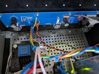
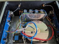
Back again, the values are staying stable now Jeej, only the output seems to be off of 10 too 12 decibel.
The values are on both the boards 468 mv at R1, only one channel give a lower output.
Things i tried:
Attached some photos of the board and the overview.
Any ideas how to troubleshoot this?
The values are on both the boards 468 mv at R1, only one channel give a lower output.
Things i tried:
- Other speakers, and switch the speakers but result is the same
- With a pre amp (diy nutube B1) or without.
- Checked the connections on the board, and the wiring.
Attached some photos of the board and the overview.
Any ideas how to troubleshoot this?
Attachments
So all voltages are good, and offset is at or near zero?
But you are getting sound but one channel has low output.
Suggestions:
- check and compare R5 and R6 between channels. Also check the solder joints of the low signal channel.
- when you checked the wiring and connections and changed preamp, did you swap input channels and swap input interconnects to the low signal channel?
- if still a problem, with both channels connected to a source, play a signal through the amplifier (download a 1kHz tone:Test tone download).
Set your multimeter to AC Voltage, connect the black probe to amplifier ground, and measure the AC Voltage at both ends of R5, R11, R12, and at amplifier speaker output.
Thank you Ben! I think i made to many mistakes to build this. Couple of year ago i soldered it and dont know that i needed to measure all the components and did a switch a 0.47 with a 47k resitor. So the restisor on place R6 was 0.47 and on the other board it was 47k on place R12.
I think i made a second stupid mistake, When i measured the R12 (with the amp on) i heard a sisss sound, after desolder the wrong resistors and placed back in the correct place it seems that Q1 isn't get any voltage anymore 0.00, the offset is also set to 20v and not getting it lower with the pot. Is the mosfet damaged or is there another component what is wrong.
I think i made a second stupid mistake, When i measured the R12 (with the amp on) i heard a sisss sound, after desolder the wrong resistors and placed back in the correct place it seems that Q1 isn't get any voltage anymore 0.00, the offset is also set to 20v and not getting it lower with the pot. Is the mosfet damaged or is there another component what is wrong.
So some good news and bad news.
Looks like the low output issue is resolved.
The bad news is that you may have toasted Q2. What is the voltage across R2? Does the voltage across R2 change as you adjust P2? What is the voltage across Q2 gate and source? Does that voltage change as you adjust P2?
Looks like the low output issue is resolved.
The bad news is that you may have toasted Q2. What is the voltage across R2? Does the voltage across R2 change as you adjust P2? What is the voltage across Q2 gate and source? Does that voltage change as you adjust P2?
Had been interested in the Pass Labs stuff for a good while. Spurred by a successful build of a pair of ACA Redux amps I was curious to see what its bigger brothers might offer. Skeptical of my own skills in working with mains power, transformers/power-supplies, I came across and picked up an F6 that was already built - by @wdavis009. It was a most impressive and excellent build, in a Deluxe 4U chassis. Was floored by how good it sounded, it replaced a Class D audio amp, powering my set of Mirage M3's. I thought I might commission an artist friend to paint the front panel of the chassis, asking for a space theme with a logo I had previously created. Was very much pleased with the end result, thought I might share it here. The artist is Grace Noel, from Denver CO.

R2 is nice 0.503 when i adjust it increase or decrease. Q2 stays on 0.021v after adjusting the p2 or p1So some good news and bad news.
Looks like the low output issue is resolved.
The bad news is that you may have toasted Q2. What is the voltage across R2? Does the voltage across R2 change as you adjust P2? What is the voltage across Q2 gate and source? Does that voltage change as you adjust P2?
So R2 measured 0.503V, and adjusting P2 caused it to change? That is good because then current is flowing through Q2 and P2 is working to control the current, although previously (post #4,810) you said that the offset was 20V, which is a sign that Q2 was not conducting.
Measure the offset again, and make sure that the black probe is at Ground and the red probe is at the speaker output, and note the polarity of the measurement.
Where at Q2 did you measure 0.021V?
Also please be concise when reporting. Always include unit of measure (V, mV, A, mA, etc), and state what you what you measured and what you adjusted if adjustment was made. Example of what not to say, "R2 is nice 0.503 when i adjust it increase or decrease".
Since you are getting voltage at R2 and P2 adjustments seem to be working, then what is the voltage across R1 and and does that change if you adjust P1, and what happens to the offset. And does Q1 Vgs change if you adjust P1, and what is the value of Vgs
Measure the offset again, and make sure that the black probe is at Ground and the red probe is at the speaker output, and note the polarity of the measurement.
Q2 stays on 0.021v after adjusting the p2 or p1
Where at Q2 did you measure 0.021V?
Also please be concise when reporting. Always include unit of measure (V, mV, A, mA, etc), and state what you what you measured and what you adjusted if adjustment was made. Example of what not to say, "R2 is nice 0.503 when i adjust it increase or decrease".
Since you are getting voltage at R2 and P2 adjustments seem to be working, then what is the voltage across R1 and and does that change if you adjust P1, and what happens to the offset. And does Q1 Vgs change if you adjust P1, and what is the value of Vgs
Hello Ben,
Thanks for your help so far, sorry for the lack of measurement information and i think i supplied wrong information. Q1 is damaged instead of Q2.
Give it a new try here, measurements are after 15 minutes on board with a low voltage on Q1.
Measurement 1 (no adjustment made):
Offset: -20.2v
R1: 0.475v
R2: 0.470v
Q1: 0.024v (black probe on the gate and red on the source)
Q2: 4.29v (black probe on the gate and red on the source)
Measurement 2 (turned P1 anti clockwise):
Offset: -20.4v
R1: 0.475v
Q1: 0.024v (black probe on the source and red on the gate )
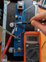
See the video of R1 and adjustments of P1 and P2.
Hope I am complete with the measurement.
Thanks for your help so far, sorry for the lack of measurement information and i think i supplied wrong information. Q1 is damaged instead of Q2.
Give it a new try here, measurements are after 15 minutes on board with a low voltage on Q1.
Measurement 1 (no adjustment made):
Offset: -20.2v
R1: 0.475v
R2: 0.470v
Q1: 0.024v (black probe on the gate and red on the source)
Q2: 4.29v (black probe on the gate and red on the source)
Measurement 2 (turned P1 anti clockwise):
Offset: -20.4v
R1: 0.475v
Q1: 0.024v (black probe on the source and red on the gate )
See the video of R1 and adjustments of P1 and P2.
Hope I am complete with the measurement.
Attachments
There is definitely something off with Q1. Do you have another mosfet for replacement?
Remove Q1 and before replacing it, power up and check the voltage across the zener, Z1. If it is a 5.1V zener, it should measure 5.1V +/- 5%.
By the way, when you measured the mosfet Vgs, if you had the black probe on the gate and red probe on the source, the measured voltage should be negative.
Remove Q1 and before replacing it, power up and check the voltage across the zener, Z1. If it is a 5.1V zener, it should measure 5.1V +/- 5%.
By the way, when you measured the mosfet Vgs, if you had the black probe on the gate and red probe on the source, the measured voltage should be negative.
Setting the Bias and Offset - General question for clarity. Measuring Temperature, Fine Tuning Bias and Offset and Equal Measurements of Boards
Hopefully quick questions. I did search the forum and cannot locate a particular answers. This is related to the F6 Rev 2 boards.
1. When setting the Bias and Offset, we are seeking to increase the voltage (measured at R2 0.47 Ohm 3W resistor) to keep under the following conditions (from post #1)
a. Heatsink of 55C and/or Transistor pin 2 65C
b. Total bias, both channels (in watts) of no more than 1/2 the power transformer’s VA
c. 1/2 the maximum dissipation (in watts) of the output device. In the case of the IRFP240, it’s a 150W device, so no more than 75W
Focusing on condition a., when measuring the heatsink termperature (using an IR Thermometer), I assume we are measuring the temperature on a single board as shown in the build guide at the highest temperature point on the heatsink? For me at 609 mV bias and 0 mV offset, I measured a maximum of 50 degrees C in the area around Q2 on the outside of the heatsink. I am also is a somewhat cool room that helps the heat dissipation.
I am thinking that I will use the 5 Degree C buffer when I test the assembled unit before closing the unit up. Meaning everything put together and the top resting in place with the probes in the case to model the final product conditions.
In measuring the Transistor pin 2, is this referring to Q1, Q2 or Q3/Q4? For me these had much lower temperatures.
In condition b. I have an Antek 3218 300VA 18V transformer as suggested. Thus the total bias should be no more than 75W. So in my case 0.609V/0.47Ohms = 1.3A. And with the rail at 24V, my unit is producing 31W a side or 62W total. So far, so good.
2. Since the probes attached for the Offset do influence the Bias, is there any need to detach these when fine tuning the Bias? Likewise, is there any need to detach the Offset probes to fine tune the Bias? I'm not sure if am getting overly picky here.
3. The objective is to acheive equal Bias and Offset on both boards as long as the conditions a., b., and c. are maintained even though there might be some variations, e.g., temperature readings that are 2-3 Degrees different.
I am more of a cookbook builder rather than modifier at this point.
Thanks all and I really appreciate the work of 6L6 and the other moderators. Jeffri
Hi Jeffri,Focusing on condition a., when measuring the heatsink termperature (using an IR Thermometer), I assume we are measuring the temperature on a single board as shown in the build guide at the highest temperature point on the heatsink? For me at 609 mV bias and 0 mV offset, I measured a maximum of 50 degrees C in the area around Q2 on the outside of the heatsink. I am also is a somewhat cool room that helps the heat dissipation.
I am assuming you are using a Modushop 4U/300 and if so, what you are stating is completely fine. You can even venture up to 55degrees but I am most comfortable at 50 degrees. Why? Not because I am worried about frying the output MOSFETs. It has to do with safety from a medical standpoint to minimize accidental burns and such. If you can keep your hand on that heatsink for a good 5 seconds you are good (which might happen if a child or small pet were to touch it).
Q1, and Q2, i.e. the output MOSFETS. Q3 and Q4 are the input jfets and they are not the ones passing 1.3A of current! What you are most concerned with is keeping the dissipation of those output MOSFETs at a safe level to ensure a long life.In measuring the Transistor pin 2, is this referring to Q1, Q2 or Q3/Q4?
No, there is not. Keep both probes on, it’s a seesaw effect.2. Since the probes attached for the Offset do influence the Bias, is there any need to detach these when fine tuning the Bias? Likewise, is there any need to detach the Offset probes to fine tune the Bias? I'm not sure if am getting overly picky here.
You do want both boards to have biases relatively close to each other but don’t get overly anal. It doesn’t make a hill of beans difference in the distortion curves particularly the harmonic distortion. In example, if one board is at 1.25A and the other is 1.3A, no big deal. Most diy’ers are much more persnickety and they will be much much closer. Another important point is don’t get too anal about achieving an offset of 0.0 volts. If you are under 25 millivolts (0.025 volts) for both boards you’re fine.
I want to congratulate you for stating the bias as a current value (i.e. in amps) as it should be stated instead of millivolts as so many here do. Without knowing the resistor value where you are measuring the bias (i.e. 0.47 ohms in your example), nobody knows the actual current (and it’s really up to the author to state it or do the calculation!).
Enjoy your new F6!
Best,
Anand.
A relative is building the F-6 (my fault, I encouraged him!) I mentioned that there was an update but thought that it was only one pair: R7 and Z1 that needed to be changed.
I then actually LOOKED at the schematic and can see that the circuit is mirrored so it’s both R7, R8 and Z1, Z2, right?
Zen “Zener” Mod will be proud of me!
I then actually LOOKED at the schematic and can see that the circuit is mirrored so it’s both R7, R8 and Z1, Z2, right?
Zen “Zener” Mod will be proud of me!
- Home
- Amplifiers
- Pass Labs
- F6 Illustrated Build Guide