62.
All of the bias circuits shown produce very similar results.
Thank you - some contemplation and mulling is needed for me tonight
") cheers
cheersok
maybe I'm too hysteric regarding DC through coil (even in range of uA) , but another thing which bugs me is possible variable loading of secondary,due to variable impedance of gate itself and very possible not enough loading ;
...
from experience - I know that sole worse thing than unloaded secondary is just heaven fallen on your head
ask Vikings
use highish value of trimpot , to avoid too much loading of secondary , or insert at least few K resistor in series with wiper

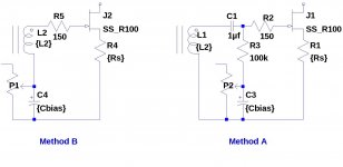
Here is a summary of the two bias methods. Method A places the bias circuit in series with the transformer secondary. Method B places a capacitor in series with the gate drive and biases the gate through a high value resistor.
In both methods, there is a capacitor in the path from the bottom of the source resistor to the gate. Method B probably has the advantage that the bias generator is influenced less by the parasitic currents through the tranformer.
Attachments
How about this?
yes
freq. sweep on actual prototype will tell do you need to alter value of 100K resistor , to achieve best freq. linearity
yes
......will tell do you need to alter value ........
in fact - there is no doubt - you'll need to alter that value
besides that - we are speaking about low impedance coils here - feel free to use greater value for C1 ; that's at least what I'll do
10uF Silmic + 1uF MKC is my poison
.... Method B probably has the advantage that the bias generator is influenced less by the parasitic currents through the tranformer.
what you mean with parasitic currents ?
loading of secondary is of most importance here
in fact - there is no doubt - you'll need to alter that value
besides that - we are speaking about low impedance coils here - feel free to use greater value for C1 ; that's at least what I'll do
10uF Silmic + 1uF MKC is my poison
Is it possible you meant capacitors C5 and C6 in series with the gate resistors instead of C1? In post 739, C1 (and C4) are capacitors I added to simulate the internal JT-123-FLPCH transformer parasitics: 18nf coupling of both primary to secondary windings. C1 just happens to also be where a capacitor would be needed in the feedback path to "tune" the phase margin.
what you mean with parasitic currents ?
loading of secondary is of most importance here
My reference to parasitic currents is to the AC current due to the capacitance between windings. Consider the upper secondary winding L2 in bias method A. The bottom end of the winding follows Vout + Vbias. C1 is the secondary to primary capacitance added to the simulation to model the inter-winding parasitic capacitance. The parasitic current through C1 will be I=C*dv/dt, which will have a loading effect on the bias generator.
In Bias Method B, the bias generators are not loaded by the parasitic currents.
Is it possible you meant capacitors C5 and C6 in series with the gate resistors instead of C1? In post 739, C1 (and C4) are capacitors I added to simulate the internal JT-123-FLPCH transformer parasitics: 18nf coupling of both primary to secondary windings. C1 just happens to also be where a capacitor would be needed in the feedback path to "tune" the phase margin.
sorry - my mistake - I wrote wrongly C1 , meaning on C2, all the time
so - C7 and C2 are right ones
I don't think you'll need any compensation cap -they're rarely needed in that range of impedance (common repeaters)
yes
freq. sweep on actual prototype will tell do you need to alter value of 100K resistor , to achieve best freq. linearity
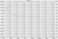
Here is a frequency sweep for the schematic in post 739. The lower trace is the phase.
Attachments
My reference to parasitic currents is to the AC current due to the capacitance between windings. Consider the upper secondary winding L2 in bias method A. The bottom end of the winding follows Vout + Vbias. C1 is the secondary to primary capacitance added to the simulation to model the inter-winding parasitic capacitance. The parasitic current through C1 will be I=C*dv/dt, which will have a loading effect on the bias generator.
In Bias Method B, the bias generators are not loaded by the parasitic currents.
agree , at least partially
anyway - issue of proper secondary loading is of much greater importance
that's just plain impossible when one side of sec is looking just in gate
so - that's the main factor for choosing in which way to connect them
Yes, it is probably good to use larger values for C2 and C7. With C2 and C7 at 10uf, 25 watts output, and a 20Hz signal the simulation shows 3.5mV p-p across C2 and C7. Increasing C2 and C7 to 100uf reduces the "ripple" by a factor of 10, but doesn't appear to significantly decrease the THD.sorry - my mistake - I wrote wrongly C1 , meaning on C2, all the time
so - C7 and C2 are right ones
I don't think you'll need any compensation cap -they're rarely needed in that range of impedance (common repeaters)
Here is a frequency sweep for the schematic in post 739. The lower trace is the phase.
sim or real McCay ?
if sim - just forget it
you need real one to play with
The frequency sweep plot was from LTSpice. I performed the same freq sweep with different values for R12 and R13, but the effect was rather minor.sim or real McCay ?
if sim - just forget it
you need real one to play with
Yes, I do not believe that the simulation properly captures the transformer loading behaviour. It is (past) time to wire together the circuit. I think I have enough of the parts now.
in fact - there is no doubt - you'll need to alter that value
besides that - we are speaking about low impedance coils here - feel free to use greater value for C1 ; that's at least what I'll do
10uF Silmic + 1uF MKC is my poison
Holy cow! I cannot find a 1uF MKC (Polycarbonite film cap) for less than about US $20.
Holy cow! I cannot find a 1uF MKC (Polycarbonite film cap) for less than about US $20.
maybe you should be looking for polycarbonate -- at any rate, i bought a fellow's stock of 10u/50V sprague polycarbonate caps several years back -- Tech DIY Company Store
Holy cow! I cannot find a 1uF MKC (Polycarbonite film cap) for less than about US $20.
25x MKC Folien-Kondensator axial 1uF 63VDC 7,5x19mm ; MKC18605100668 | eBay
maybe I'm too hysteric regarding DC through coil (even in range of uA) , but another thing which bugs me is possible variable loading of secondary,due to variable impedance of gate itself and very possible not enough loading
I suppose it's possible to over-think this.
I just hook these things up and see what I get.
in fact - there is no doubt - you'll need to alter that value
besides that - we are speaking about low impedance coils here - feel free to use greater value for C1 ; that's at least what I'll do
10uF Silmic + 1uF MKC is my poison
Anyone have an opinion of the Vishay Roederstein Metallized Polypropylene Film Capacitor (MKP)?
- Home
- Amplifiers
- Pass Labs
- F6 Amplifier