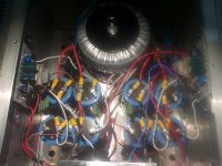
Finished building the F6 today. Taking a break from troubleshooting.
Power supply functioning perfectly at 25.1v all around.
Voltage across R14 and CRC resistors is only .30v. Can't get it to reach 1.2v.
Also one of the channel's offset is around 18-19v, with little change when adjust.
I used blue LEDs I had on hand, three different makes.
Should I have used the same make on all four per channel?
I didnt think developing 1.2v with two blue LEDs would be a problem.
Attachments
Finished building the F6 today. Taking a break from troubleshooting.
Power supply functioning perfectly at 25.1v all around.
Voltage across R14 and CRC resistors is only .30v. Can't get it to reach 1.2v.
Also one of the channel's offset is around 18-19v, with little change when adjust.
I used blue LEDs I had on hand, three different makes.
Should I have used the same make on all four per channel?
I didnt think developing 1.2v with two blue LEDs would be a problem.
Check the voltage across each of the LEDs. Each should be around 3V-3.5V. If they are much different from that, they are either miswired or current starved.
Are the resistors feeding them from either side of the 24V supply much greater than about 5k? That could be one reason. Make sure they are all installed in the correct polarity.
Also, all of the LEDs MUST be identical, as they are in series and are thus forced to carry the same current. If they are not the same type, forcing both of the two series LEDs to have the same current could make the two LEDs have very different voltage drops.
Last edited:
Check the voltage across each of the LEDs. Each should be around 1.8V
He is using BLUE -- those average 3.3V, right?
He is using BLUE -- those average 3.3V, right?
Yes, a quick check on Digikey gives around 3V at 5mA for standard blue LEDS.
There are 4 leds per side, but one set I cant get to the leads.
However, the LEDs that can be reached read 3.1v across them in both channels, pos and neg.
So doesn't look like its starved.
That sounds good. Then I'd check the lower gate to source voltage directly, to see if it's about right. Don't let the probes slip, though.
Put the gate probe on the NON-gate side of the gate resistor, to reduce the chance of oscillation. This applies to the lower device only,
because the upper device has a different biasing arrangement that does not directly control its gate-source voltage.
Also, with the amp powered off, check the resistance from the NON gate side of the all the gate resistors to the associated gate terminals
directly (NOT at the other resistor terminal).
This reading should be the same value as the gate resistor. This test checks for a bad connection at the gate, or a bad resistor.
Last edited:
Reads ~ 47 ohm for R8 in both channels.
Reads 1.31 and 1.32 Vgs.
Sounds ok. Maybe you just need higher bias voltages. I understand that far off the optimum settings, you can get high output voltage offsets.
Read the F6 biasing procedure carefully again.
I have the instructions from BAF presentation. One place it says bias can be set from CRC resistor and read somewhere else that it can be set from R14.
I'm going to get 8 LEDs of the same brand.
Do you know if the LEDs are in series.
Thanks rayma and 6L6!
Vince
Just saw you post. It starts to warm up nicely on both chsnnels.
The toriods are large so when I turned on the dimmable overhead light the toroids started humming a bit.
Stopped when off. But we know this.
Holy $#!+. Wait!! The correct bias across is .12v??? Oh no!
Last edited:
An externally hosted image should be here but it was not working when we last tested it.
Yes, they are in series
Check your PM
I have the instructions from BAF presentation. One place it says bias can be set from CRC resistor and read somewhere else that it can be set from R14.
I'm going to get 8 LEDs of the same brand.Do you know if the LEDs are in series.
Each channel has a pair of series LEDs for each device.
Holy $#!+. Wait!! The correct bias across is .12v??? Oh no!
I think you've got it.
OK, bias settled at .118v in both channels. One channel offset is OK. Can set it and bias doesn't change.
However, on the other channel when set bias to .118, offset is around 20v. When adjusting the offset pot, the offset only moves a few .001 volts. No affect on bias.
Did I burn out the pot?
However, on the other channel when set bias to .118, offset is around 20v. When adjusting the offset pot, the offset only moves a few .001 volts. No affect on bias.
Did I burn out the pot?
OK, bias settled at .118v in both channels. One channel offset is OK. Can set it and bias doesn't change.
However, on the other channel when set bias to .118, offset is around 20v. When adjusting the offset pot, the offset only moves a few .001 volts. No affect on bias.
Did I burn out the pot?
Only one way to find out, desolder and test it carefully for proper operation with an Ohm meter
Only one way to find out, desolder and test it carefully for proper operation with an Ohm meter
Do you think anything else could cause the offset to go that high? There aren't many parts before the wiper. I'll check R3. We already checked the LEDs.
I remember when first starting the amp, everything was set to miniums.
I turned the offset pot a few times, then it ran away to 18v.
Now, with the bias set to .118v across R14 it at 20v.
Thanks guys!
- Home
- Amplifiers
- Pass Labs
- F6 Amplifier