Anybody want to go in a some to try and match. Looking at them, I wonder how linear they are at our operating range.
I bought 12, we can see if we have any matches.
Rush
Has anyone determined the temperature coefficient of the CREE at 1.5 amps? In a previous post I claimed (without rebuttal) that a source resistor could be used in the F6 for bias current stabilization vs. temperature. I am interested in the CREE for possible use in an amplifier design where a positive tempco would be useful.
What is the application you are using for measurements?
Spoken by Tapatalk.
--left picture amp with splitted resistor network in the PSU according to F6 talk
--right picture amp with not splitted resistor network in the PSU
I see no visible difference concerning the higher harmonics of the 50Hz fundamental.....
my 100Hz is fairly high....does anyone know what to do and what is the influence to the sound?
The 50Hz hum is high because of Kimber cables not shielded and the USB sound card itself.
The third picture is from the Masters device, like always much better, how does he do that? He gets better 100Hz and 200 Hz values without any splitting.... ha, ha!

Spoken by Tapatalk.
Anybody want to go in a some to try and match. Looking at them, I wonder how linear they are at our operating range.
Define your operating range -- i have a couple from a few months ago -- they really should be pulsed to test.
I plan t o trace them with a curve tracer, but limited to 2-3A. They will be used a most Pass designs, in the 20-30v range @between .5-2A. I think Ilquam may be looking at higher bias and lower Vds for his test bed. Perhaps they are well suited for that, based on what can be seen in the graphs.
This may help to start --
I don't yet have "yet" my Dekker u-tracer and the 576 is not quite up to the task...
An externally hosted image should be here but it was not working when we last tested it.
I don't yet have "yet" my Dekker u-tracer and the 576 is not quite up to the task...
Quickly hooked up to the 576 -- should have a minimum bias of 3.5V -- but you can figger it out for yourself:
interesting straight line @12V gate bias.
An externally hosted image should be here but it was not working when we last tested it.
interesting straight line @12V gate bias.
I'm "thick as a brick". Don't know what you mean.
Should have put a couple of "AA"'s in series with the gate stepper.
The vertical axis is 2 amps per division. The horizontal is 1V per division.
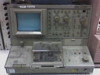
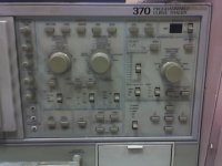
This would be a suitable instrument.
I found this in a South-Korean multinational company warehouse in Romania.
They had no idea what it is.
May be some kind of oscilloscope?
Arrgh...
Unfortunately, I may brought it home only to poor quality images.
I found this in a South-Korean multinational company warehouse in Romania.
They had no idea what it is.
May be some kind of oscilloscope?
Arrgh...
Unfortunately, I may brought it home only to poor quality images.
Attachments
Last edited:

What is the application you are using for measurements?
Spoken by Tapatalk.
a Mac with Electroacoustic Toolbox....
because there is no visible difference I decided to measure again, I cannot believe it, because I hear a clear difference....
Just a matter of ordering them from Profusion. Little expensive, but great deal less than SS.
Two I would recommend.
ECW20N20-Z
ECW20P20-Z
Nice, I will order some to try in a F5...
Tea and others who've built this - how are you finding the offset setting and drift on the F6?
Bias and offset settings correlate. Once you have found the right balance, both keep very stable after a certain warm-up phase.
My F6 has a total power consumption of between 250W and 260W when started cold and decreases to about 220W after one hour or so. These consumption figures include the losses in the transformers, the rectifiers and in the regulated power supplies.
I built it strictly dual mono with considerably dimensioned heat sinks to achieve a relative constant temperature during its operation time. There is no degeneration of the power JFETs implemented.
Last edited:
- Home
- Amplifiers
- Pass Labs
- F6 Amplifier