It needs a proper heatsink and case before anything else..
Power supply isn't appropriate.
Because it is a huge torid, (courtesy of forum member Sajti.) an 1kVA coil on 1.5kVA core,
it wouldn't be a problem, but It has 2x25VAC secondaries.
It is a little bit high, so I must have to reduce input with Schuntermann, to cc. 170V., so I got 2x23VDC.
(Other piece of identical toroid drives my double stereo F4 it can be seen on pic, many thanks to Sajti again!)
Other problem, while it has laying on the floor, there isn't any noise, hiss or buzz.
Now it has some buzz and I don't like it.
So, many things to do yet.
I think the MSB Platinum Link is beginning to recover after the surgery.
Too bad there are a lot of smart-a€€ (I haven't found a dollar sign) who can tell him everything except the MSB DAC.
You know the feeling, now I can't decide what to listening because everything is a new adventure.
Too bad there are a lot of smart-a€€ (I haven't found a dollar sign) who can tell him everything except the MSB DAC.
You know the feeling, now I can't decide what to listening because everything is a new adventure.
I think, I remains with John Surman, even there are splashing salivas.
https://www.youtube.com/watch?v=VYFlNdKIUgY
https://www.youtube.com/watch?v=VYFlNdKIUgY
Hello,
I red all your posts and at the end I've decided, it's time to grow up, I've build the parts to transform my F2j in a F6 amp with R100 .
So at the end you use a F6 output degeneration circuit or a Variable 2nd armonic?
And instead of the blue leds, do you prefer LM329?
Do you make any other modification?You put R11 and R12 in place as current limiter?
Thanks a lot in advance for your help.
Ciao
Guglielmo
Hey Guglielmo,
Thank you for your interest!
I'm trying to answer your questions:
1., I have built it according schematic in first post, F6 with variable second harmonic.
2., Yes, I prefered LM329, it is a good idea, thanks Buzz!
3., I didn't use R11, R12 it is the only modification.
(Because stock F6 board don't have place for.)
Not yet been prepared, waiting for appropriate housing and PS.
I do not know how long to wait because of many other projects.
Now collecting parts for a proper network server for musics and pictures.
Kind regards,
Gyuri
John Surman his spit-and-snot blowing into his sax now.
Thank you for your interest!
I'm trying to answer your questions:
1., I have built it according schematic in first post, F6 with variable second harmonic.
2., Yes, I prefered LM329, it is a good idea, thanks Buzz!
3., I didn't use R11, R12 it is the only modification.
(Because stock F6 board don't have place for.)
Not yet been prepared, waiting for appropriate housing and PS.
I do not know how long to wait because of many other projects.
Now collecting parts for a proper network server for musics and pictures.
Kind regards,
Gyuri
How is it now Gyuri?
John Surman his spit-and-snot blowing into his sax now.
Last edited:
Hi Gyuri,
I don't want to capture your thread, I hope you don't mind!
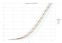
Here the guys said "just show us the transconductance curves of your JFets, and we say where to mount so it sounds best!"
@all
This is what I did, and I learned that even if you use quality measurement cables, check their connectors for even slightly corrosion. (I measured them really more than 4 times, this is no fun, until I realized the contacts were my bug in my setup.)
So, I have 6 JFets, which 4 to use and in which position? Many thanks!
I don't want to capture your thread, I hope you don't mind!
Here the guys said "just show us the transconductance curves of your JFets, and we say where to mount so it sounds best!"
@all
This is what I did, and I learned that even if you use quality measurement cables, check their connectors for even slightly corrosion. (I measured them really more than 4 times, this is no fun, until I realized the contacts were my bug in my setup.)
So, I have 6 JFets, which 4 to use and in which position? Many thanks!
Attachments
Last edited:

Dear Buzz,
I really have done at least four times the measurement of all devices. very strange is, that they vary all a lot. I let the heatsink settle at 2 amps, then dialled in the Vgs for the corresponding Id points.
These curves are the smoothest I've got.
Temperature variation is of cause there, but all measurements were taken in "short" time, as quickly as possible.
I read that it's good to put the one with higher transconductance on top, but how much would be optimal? Just because I've two pairs with the same distance in the curves.
I appreciate your comments and thoughts a lot, thanks.
Regards,
Matthias
Pick the 4 with the closest curve shapes. Because they are biased by a voltage reference, it will not matter that they may operate at slightly different VGS values. By having fets that are more similar, you will have an easier time tweaking a circuit through other means, I.e. Source resistor variation and point of feedback.
- Status
- This old topic is closed. If you want to reopen this topic, contact a moderator using the "Report Post" button.
- Home
- Amplifiers
- Pass Labs
- F6 amp with SemiSouth SJEP120R100