Hi John,
as far as I can see Patrick perfectly answerd your questions already.
Our next step will be to integrate this protection board into
the functional model I have posted in post #654
So we are aiming for a fully qualified functional model baseline
before we are going to build the real amps.
Markus
as far as I can see Patrick perfectly answerd your questions already.
Our next step will be to integrate this protection board into
the functional model I have posted in post #654
So we are aiming for a fully qualified functional model baseline
before we are going to build the real amps.
Markus
Now it should be OK.
You may also use LSP2+ instead of LSP1+ (only + as they are all common) if it makes life easier.
Refer back to the schematics of Alexis.
Patrick
Yes indeed that will be a neater solution
")
Many thanks once again Patrick.
Hi John,
as far as I can see Patrick perfectly answerd your questions already.
Yes he has, first time round, I didn’t double dip
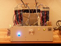
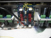
F5X proto II, protection board integrated
Our first protection board is now fully integrated in our F5X proto II.
The integration was straight forward, mainly mechanical and electro-mechanical work, which is also fun.
For sake of consistency I think I should report the list of deltas w.r.t. the original XEN audio configuration:
1) The rush-in current limiter NTCs are not in yet because I do not have them availabe yet. Instead I helped myself with two 100Ohms resistors (one for each transformer) bridging the mains relays. So right after switching on the mains switch the caps in front of the regulator board are gently loaded via the resistors. When the start-up delay time has passed the caps are at operating voltage already and the resistors are bridged by the mains relays.
2) The mute relays on the amp input board are not in yet. The startup behavior I have seen on my analog scope is so smooth and well-behaving, that I am not sure if I need the mute relays at all. Next step I´ll take some traces with my digital scope and then I will decide if I will integrate the mute relays.
3) The amplifier boards still do not have current limiters to protect the power devices in the case of a short-cut across the speaker terminals. I am a bit concearned about loss of audio performance but I have to admit that I do not have experimental evidence. Maybe I should think off a modification of the proto that facilitates a one by one test with and without current limiters.
Has somebody else related experiences?
4) The input signal is still single ended.
This configuration I have tested today.
Everything works as expected.
( Qualitative results only, measurements will follow)
Startup:
Smooth, no rush-in currents. no switch-on bumps on the speakers.
Speaker Protection:
Checked
Markus
Attachments

If you use regulators, slow start is ensured. But it is still good practice to have the NTC.
The NTC at steady state has less resistance than a single relay contact.
And you WILL need the input shunt in case of trip, especially if you use a shunt trip at the speaker end (like I do).
It has been widely reported that the current limiting circuit has negative effect on SQ.
Since you already have full blown protection, I would leave that out.
And you are NOT giving the amp justice by not using a balanced source, which I know you have.
Patrick
Hi All,
First of all happy holidays to everybody. I am finding some time to complete this project, late nights, mo other options.
Anyway, one dumb question: I understand that the mute board is connected only to the input board. Is it correct or the wires have to go all the way down to the main board?
Thanks,
D
The way I see it now is: mute common only between input and mute board, the rest all the way through the main board. Correct ?
Thanks,
D.
Correct.
Is there a preferred position of the mute board? I mean in the lower or higher part of the chassis.
Thanks,
Davide
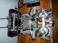
I’ve chosen the top, and routed my protection wiring accordingly.
Further, I found starting with the front panel protection wiring and routing it through the amp first worked very well.
Once hooked up to all the relays I was able to run another test of the protection circuitry in its final position.
I then hooked up the outputs and inputs. There’s not much now left to do until I receive the regulator conversion kit.
Tip: The fuse holder must have a fuse inserted to release it’s screw top cap. With out a fuse inserted and the cap screwed in place I stripped mine and ruined it
Attachments
Very neat wiring John.
Seems that the input wires are as thick as the output ones ??
One suggestion if I may :
Those glued-on plastic wire clips probably would not last 10 years at 60°C.
I should consider not using double sided foam tapes to fix them, but M3x6 screws.
Which means you need to tape some blind holes on the heat sink and the front panel, unfortunately.
Patrick
.
Very neat wiring John.
Seems that the input wires are as thick as the output ones ??
One suggestion if I may :
Those glued-on plastic wire clips probably would not last 10 years at 60°C.
I should consider not using double sided foam tapes to fix them, but M3x6 screws.
Which means you need to tape some blind holes on the heat sink and the front panel, unfortunately.
Patrick
.
Thanks Patrick,
I did consider the longevity of these clips, I knew there life expectancy at temp would be compromised, I plan to keep an eye on this
Edit; Oh yes, those inputs, more insulation and shielding than thicker conductors (18awg), the outputs are occ 16 awg... haha
Last edited:
Patrick,
many thanks for your remarks.
As soon as I will have the NTCs available I will integrate them.
The resistors are only a temporary solution, otherwise about every
second amp start-up we are sitting in the dark because the fuse in the
e-power cabinet trips due to the rush in currents ( > 16A)
Well, I think I got your point and I also understand that you do not like to have relay contacts in the signal line.
But the concept of a shunt trip at the speaker end I do not fully understand.
The amp is a voltage output amp of which output voltage is never exactly zero, even when the input voltage is shunted by the mute relays. So without a current limiter you will get a shunt current that is determined by output voltage offset of the amp and the sum of relay contact resistance + amp output impedance. Consequently you need to get the output voltage offset small enough (over lifetime) and the relay contact resistance plus amp output impedance high enough (also over lifetime) to make sure that the shunt trip will never destroy your power devices.
Therefor I guess this configuration is only an option for those who have enough sets of spare devices, isn´t it?
The majority of DIYers like me do not have this luxery.
I am currently considering an alternative concept and I am wondering what will be wrong this:
Why not shunting the power supply lines between regulator output caps and the amplifier board? Thanks to the cap-less amp design there is no energy stored in the amplifier. This means from speaker protection persective shunting the power supply of the amplifier board should be as good as shunting the amplifier outputs. In addition I would insert fuses in the power supply cables right in front of the shunt relays. The fuses will trip in both cases, when the speaker protection trips but also when the amp output currents exceed critical levels due to an external short cut.
Certainly you and others have already though this option through and there must be a critical point that I have missed. All remarks and hints are appreciated.
Many thanks for your advice. I will happily leave that out.
Yes, indeed. I´ll think about how to interface the balanced source to the proto. Tomorrow the local electronic shop here in town will have open, so I could get the missing parts.
The need for an appropriate preamp becomes more and more apparant
Markus
many thanks for your remarks.
If you use regulators, slow start is ensured. But it is still good practice to have the NTC.
The NTC at steady state has less resistance than a single relay contact.
Patrick
As soon as I will have the NTCs available I will integrate them.
The resistors are only a temporary solution, otherwise about every
second amp start-up we are sitting in the dark because the fuse in the
e-power cabinet trips due to the rush in currents ( > 16A)
And you WILL need the input shunt in case of trip, especially if you use a shunt trip at the speaker end (like I do).
Patrick
Well, I think I got your point and I also understand that you do not like to have relay contacts in the signal line.
But the concept of a shunt trip at the speaker end I do not fully understand.
The amp is a voltage output amp of which output voltage is never exactly zero, even when the input voltage is shunted by the mute relays. So without a current limiter you will get a shunt current that is determined by output voltage offset of the amp and the sum of relay contact resistance + amp output impedance. Consequently you need to get the output voltage offset small enough (over lifetime) and the relay contact resistance plus amp output impedance high enough (also over lifetime) to make sure that the shunt trip will never destroy your power devices.
Therefor I guess this configuration is only an option for those who have enough sets of spare devices, isn´t it?
The majority of DIYers like me do not have this luxery.
I am currently considering an alternative concept and I am wondering what will be wrong this:
Why not shunting the power supply lines between regulator output caps and the amplifier board? Thanks to the cap-less amp design there is no energy stored in the amplifier. This means from speaker protection persective shunting the power supply of the amplifier board should be as good as shunting the amplifier outputs. In addition I would insert fuses in the power supply cables right in front of the shunt relays. The fuses will trip in both cases, when the speaker protection trips but also when the amp output currents exceed critical levels due to an external short cut.
Certainly you and others have already though this option through and there must be a critical point that I have missed. All remarks and hints are appreciated.
It has been widely reported that the current limiting circuit has negative effect on SQ.
Since you already have full blown protection, I would leave that out.
Patrick
Many thanks for your advice. I will happily leave that out.
And you are NOT giving the amp justice by not using a balanced source, which I know you have.
Patrick
Yes, indeed. I´ll think about how to interface the balanced source to the proto. Tomorrow the local electronic shop here in town will have open, so I could get the missing parts.
The need for an appropriate preamp becomes more and more apparant
Markus
I tested the first channell with a lab psu, with grounded X.
When do you advice to float the X? I understand that I could trim the voltage output exactly like the one I am testing with, using the regulators. As I have 16V secondaries, what voltage do you think I shouls aim for to valance between the dissipation in the amp and in the regulators?
Thanks,
Davide
Thanks
The audio part worked with no issues!!!
Also tested with the generator. Surprised that the input voltage does not affect much the bias.
If I did not have two holigans running around, I would test it with some music.
D.
Also tested with the generator. Surprised that the input voltage does not affect much the bias.
If I did not have two holigans running around, I would test it with some music.
An externally hosted image should be here but it was not working when we last tested it.
D.
> Therefor I guess this configuration is only an option for those who have enough sets of spare devices, isn´t it?
Yes.
> Why not shunting the power supply lines between regulator output caps and the amplifier board?
Probably will work equally well.
Why not try it with a dummy load at the output of the PSU and see what happens ?
You still need to switch off mains of course.
Patrick
Yes.
> Why not shunting the power supply lines between regulator output caps and the amplifier board?
Probably will work equally well.
Why not try it with a dummy load at the output of the PSU and see what happens ?
You still need to switch off mains of course.
Patrick
Last edited:
Congratulations Davide.
> When do you advice to float the X?
When you are happy that it works as intended in grounded X, biased adjusted at steady state.
> I understand that I could trim the voltage output exactly like the one I am testing with, using the regulators.
Yes, by choosing the right Zener diodes.
> As I have 16V secondaries, what voltage do you think I shouls aim for to valance between the dissipation in the amp and in the regulators?
Try 18 voltage.
And I was told that 1.6A bias will help reducing heat sink temperatures without compromising sound.
Patrick
Congratulations Davide.
> When do you advice to float the X?
When you are happy that it works as intended in grounded X, biased adjusted at steady state.
Patrick
What I mean is: do I have to ground the X every time I want to modify the bias ?
I'd like to make all the adjustment with the lab psu, but the output voltage of the real pus is unknown at the moment.
Additionally, can you elaborate a bit on how to trim the output voltage. From what you wrote, I may need to buy some additional parts for it.
One thing: on the Fuk resistors you may find a number like 437. This is the voltage drop of your resistor with 2 A load.
Thanks,
Davide
No. Once you have it set up once, you can keep it floated.
You can also use an X which is connected at the intersection, but not grounded.
Like it Nelson's balanced F5T.
The regulator output voltage is determined by the Zener diode in series with a 1N4148.
This minus the Vgs of the MOSFET will give you the regulator output voltage.
You can of course choose whatever combination of the two (including LEDs to replace the SMD 1N4148).
Note that Zener has a few % tolerance, so you might need to hand pick if you want to be exact.
Alternatively you can wire yourself a TL431 and then set the exact voltage with a trimpot.
But I am not so fussy with exact rail voltages, so I did not bother.
Could one of those (John?) who finished building and testing the protection board kindly post a pointer to the relevant documents (BoM, Circuit Description, ...., etc.) ?
Then the others know for sure what to follow blindly (which I never want to endorse).
Many thanks in advance.
Patrick
Firstly info on the protection board :
http://www.diyaudio.com/forums/pass-labs/208880-f5x-euvl-approach-build-thread-10.html#post3399396
http://www.xen-audio.com/documents/f5x/130223 Protection Board F5X Chpt 1.pdf
(Page 6)
http://www.diyaudio.com/forums/pass-labs/208880-f5x-euvl-approach-build-thread-13.html#post3524365
http://xen-audio.com/documents/f5x/130603 Protection Board F5X Test.pdf
http://www.diyaudio.com/forums/pass-labs/208880-f5x-euvl-approach-build-thread-13.html#post3512409
(The pdf already has the new values.)
Happy New Year,
Patrick
- Home
- Amplifiers
- Pass Labs
- F5X -- the EUVL Approach - The Build Thread