An aluminum rear panel, being rather thin, will tend to warp or bend, especially with a bunch of holes in it.
Using a chassis without a bottom sub-panel (like for preamps, etc.) means you have to drill a bunch of holes in a steel panel.
And the paint does flake off when doing that.
Using a chassis without a bottom sub-panel (like for preamps, etc.) means you have to drill a bunch of holes in a steel panel.
And the paint does flake off when doing that.
Drilling and cutting mild steel sheet metal is not a challenging affair. The modushop panels are 1mm? That = 19ga. There's no need to bother with cutting oil but a nice new drill bit is never a bad idea for panel work. Clamping the panel to a piece of wood to provide backing will help keep the backside of the hole clean with minimal attention (if any) needed after drilling.
Paint options (aerosol) have improved dramatically over the years and while single product Paint/etching primer products work very well and are on the shelves everywhere, I've really been impressed with rattle-can automotive paints. 2K (2 part urethane) is a little spendy @ $25-$30 can but is a hard, durable finish and the spray pattern is almost spray gun like.
I'm happy to provide more detail if it helps.
Do you have a new schematic for the PS? Can I add thermistors to my recent rev? ThanksThe latest batch of F5m Essentials has shipped to the store. There has been an alteration
to the power supply board that gives minor improvement - they do not have more capacitance
(you could of course buy larger caps that will fit the board) but I have added two thermistors
to the completion kit which allows separate RC filtering for each channel, supporting higher bias
and less supply crosstalk. Documentation to follow shortly.

Question for those of you using "normal" First Watt style power supplies with F5m. Does F5m get hot like original F5 with larger power supply?
Thought about putting my F5m kit in my F5 case, which is dual mono with twin 300 VA. But if it isn't any hotter I may as well buy a 3U for it.
Thought about putting my F5m kit in my F5 case, which is dual mono with twin 300 VA. But if it isn't any hotter I may as well buy a 3U for it.
What is the size of your current F5 case, specifically your heatsink size? What are the DC voltage rails measuring in that build? What Iq (quiescent current in amps) have you set your F5 you have now?Thought about putting my F5m kit in my F5 case, which is dual mono with twin 300 VA
The biasing options for the F5M are essentially similar to a standard F5 (I recall that the F5 was 1.3A). You have variability in biasing of course, but it seems to sound best in the 1.1A to 1.4A range as Papa has shown in the F5M build guide. If that is where your F5 is biased now, well then the F5M will be the same and produce the same amount of heat, not too different. If however, your F5 was biased at closer to 2A, and you built the F5M per the guide, then the F5M will run cooler of course. So the question really is, what are the biasing parameters of your current F5 you have in your setup?
Dissipation in watts = Total voltage across both rails X biasing current (Iq). Or P=V*I. After we know the dissipation we can calculate the approximate increase in heat sink temperature.
If the dissipation is the same for two different amp designs, then the heatsink temp rise will be the same assuming similar thermal environments, placement of Fets, and assuming the same sized heatsink and heatsink design.
Best,
Anand.
Last edited:
@Russellc It seems to me that doing the calculation has the added benefit of verifying adequate thermal conductivity of your device/heatsink junction.
Where to read the temp? For lack of any specified location that I could find, I chose top dead center of the HS, mid-way along the fin length. HSUSA 10.080 is spec's to .4C/W at 6" in length. 1.3A, 23VDC (at board) calcs out to 23.8C and the above location measured 23.4C above ambient. Close enough, despite Imperfect test conditions, to make me comfortable leaving it powered up on the bench overnight.
* I have the two channels standing vertical, in still air, fins facing each other to offset the fact that the amp isn't boxed yet. I'll repeat the test at that point
I could be wrong, but my understanding of the Modushop "steel option" is just for the top and bottom covers, which are unlikely to need any metal work. The front and back panels (and of course heat sinks too) are still aluminum. Anyone able to confirm that?
As others have pointed out, the front panel is always either 4mm or 10mm thick aluminium. The "full aluminium" version has both the top/bottom covers and the rear panel in aluminium instead of steel.
Main reason we don't drill our steel panels is because they are painted and not anodized so making holes in them would remove some of the paint and they would not look as good.
Size of case and sinks is on par with 5U. Standard 24 volt rails. Set at standard bias, ,62 mV or so IIRC as measured across resistor. Maybe their isn't that much difference as I am thinking, but I don't think it would be happy in 3U size case. I can keep hands on sinks, but they do get warm!What is the size of your current F5 case, specifically your heatsink size? What are the DC voltage rails measuring in that build? What Iq (quiescent current in amps) have you set your F5 you have now?
The biasing options for the F5M are essentially similar to a standard F5 (I recall that the F5 was 1.3A). You have variability in biasing of course, but it seems to sound best in the 1.1A to 1.4A range as Papa has shown in the F5M build guide. If that is where your F5 is biased now, well then the F5M will be the same and produce the same amount of heat, not too different. If however, your F5 was biased at closer to 2A, and you built the F5M per the guide, then the F5M will run cooler of course. So the question really is, what are the biasing parameters of your current F5 you have in your setup?
Dissipation in watts = Total voltage across both rails X biasing current (Iq). Or P=V*I. After we know the dissipation we can calculate the approximate increase in heat sink temperature.
If the dissipation is the same for two different amp designs, then the heatsink temp rise will be the same assuming similar thermal environments, placement of Fets, and assuming the same sized heatsink and heatsink design.
Best,
Anand.
Russellc
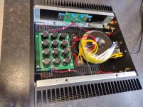
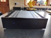
Finished and sounding great... Thanks to Nelson and all those that provided support and guidance.
Attachments
Logic800,
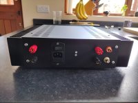
That's a sleek looking Class A amplifier you got there!
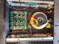
Care to share a few more details on the voltage rails, bias points? Understand that you were getting hum with the transformer at the front, and hence put it in the back?
What sort of temps are you getting in the 2U chassis?
That's a sleek looking Class A amplifier you got there!
Care to share a few more details on the voltage rails, bias points? Understand that you were getting hum with the transformer at the front, and hence put it in the back?
What sort of temps are you getting in the 2U chassis?
Silly me - indeed I got yours mixed up with another build ") :
:
https://www.diyaudio.com/community/threads/the-f6-revisited.405444/page-27#post-7657717
The diyAudio member remedied his situation by using the power switch at the back of the chassis, in fact nothing to do with transformer placement...
1.0 amp bias, +/- 24 volt rails, that means roughly 48 watts of dissipation per channel; good to hear that you have the heat under control.
What speakers are you using with the amp?
:https://www.diyaudio.com/community/threads/the-f6-revisited.405444/page-27#post-7657717
The diyAudio member remedied his situation by using the power switch at the back of the chassis, in fact nothing to do with transformer placement...
1.0 amp bias, +/- 24 volt rails, that means roughly 48 watts of dissipation per channel; good to hear that you have the heat under control.
What speakers are you using with the amp?
That looks really great! I am also using a 3U chassis but so far only have the boards ready to go. The thermal pads arrive today! Thanks @Nelson Pass !Finished and sounding great... Thanks to Nelson and all those that provided support and guidance.
I've used that Heat Sink USA 10.080. I measure with a "red dot" IR thermometer. Pretty cheap on Amazon, I think mine was 45 bucks.@Russellc It seems to me that doing the calculation has the added benefit of verifying adequate thermal conductivity of your device/heatsink junction.
Where to read the temp? For lack of any specified location that I could find, I chose top dead center of the HS, mid-way along the fin length. HSUSA 10.080 is spec's to .4C/W at 6" in length. 1.3A, 23VDC (at board) calcs out to 23.8C and the above location measured 23.4C above ambient. Close enough, despite Imperfect test conditions, to make me comfortable leaving it powered up on the bench overnight.
* I have the two channels standing vertical, in still air, fins facing each other to offset the fact that the amp isn't boxed yet. I'll repeat the test at that point
Things measure differently giving anomalies, so I usually measure different parts of whatever it is. Shiny things measure funny sometimes. Measuring the puck mosfets on XA 252, mounting screws on top are shiny, body of device is black so I measure both. Oddly, hottest spot (measured anyway) is the spot on heatsink on opposite side where mosfet is. It measures slightly higher than the mosfet itself!
I don't think that is possible, doesn't seem logical that something can heat the heatsink up hotter than it is?
Point is, measure every which way, then come to conclusion on trends I guess.
I use a K-type thermocouple on one of my two "good" meters for accuracy (source of my quoted measurements) and love my point and shoot IR but shiny things are indeed a lost cause. I'll have to try the kapton tape trick .
My favorite new tool that I didn't know I needed is a thermal cam. Its pretty accurate on most things. Its close enough to my k-probe reading on the raw aluminum sinks and random items around the shop are usually dead on but has an issue with some items. Panasonic ERX source resistors being the most extreme example to date. Consistently showing each of the 4 R's across 2 channels at ~80C. I immediately headed for the Res-spec sheet/derating info before attaching a k-probe and seeing a realistic number, 55C. Emissivity of the coating? I should put a similar current across a 3W yageo mf in the sub-ohm range and a wirewound if I can dig one up to see what happens.
Mosfet temps were much closer but still 5ish C higher than the probe I believe. I'll double check.
I picked up the thermal unit for marine DC assessments and troubleshooting and its a straight moneymaker in that environment. Small differences in heat are like billboards (the tiny current in a home GFCI lights up like a marquee).
Jfets conducting? check. Mosfets? check. High resistance connections are impossible to miss. It's my new "must have" which I'll bookend with my latest "don't waste your money" purchase, The Klein CL series DMM/Amp clamp.
.My favorite new tool that I didn't know I needed is a thermal cam. Its pretty accurate on most things. Its close enough to my k-probe reading on the raw aluminum sinks and random items around the shop are usually dead on but has an issue with some items. Panasonic ERX source resistors being the most extreme example to date. Consistently showing each of the 4 R's across 2 channels at ~80C. I immediately headed for the Res-spec sheet/derating info before attaching a k-probe and seeing a realistic number, 55C. Emissivity of the coating? I should put a similar current across a 3W yageo mf in the sub-ohm range and a wirewound if I can dig one up to see what happens.
Mosfet temps were much closer but still 5ish C higher than the probe I believe. I'll double check.
I picked up the thermal unit for marine DC assessments and troubleshooting and its a straight moneymaker in that environment. Small differences in heat are like billboards (the tiny current in a home GFCI lights up like a marquee).
Jfets conducting? check. Mosfets? check. High resistance connections are impossible to miss. It's my new "must have" which I'll bookend with my latest "don't waste your money" purchase, The Klein CL series DMM/Amp clamp.
For about $15, you can get an instant read pen thermometer from Amazon etc. The swingout needle probe slips right into one of the cylindrical holes most heatsinks have. Also works well for other tasks like adjusting bath temp for grandkids...
On heatsink below Mosfet measuring hotter than top case - if real - it's possible there is better conductivity of the die (the actual hot thing) out the base of the case than through the top.
On heatsink below Mosfet measuring hotter than top case - if real - it's possible there is better conductivity of the die (the actual hot thing) out the base of the case than through the top.
- Home
- Amplifiers
- Pass Labs
- F5m kit