turbo version
Hi UKToecutter,
I may be in the minority (not sure). But, my preferences would be:
1. Cascoded front end
2. 4 output pairs
3. Diodes off of the main heatsink - they are in the circuit to start conducting when more power is needed. They kick in when power levels beyond the class A bias are called for. So in most applications, they will probably not be conducting that often - mostly for louder low frequency transients. Therefore, I'm not sure if it's wise to keep them heated at the temperature of the main heatsink all the time.
That's my reasoning at least. Maybe there is a good argument for keeping them on the main board. But, I would think off is better. Plus, there would be more room for the 4 output pairs (if so desired) on the main sink.
Those are my thoughts,
Steve
Cascoding would be my preferences. If 3-4 outputs would be nice,
Maybe making it a jumper type board like BA2 outputs would help here.
Have it start at two outputs and have another two optional.
For that matter, can we use the BA2 output boards to our advantage here?
The diodes would need to be hard wired to it, of course.
Maybe making it a jumper type board like BA2 outputs would help here.
Have it start at two outputs and have another two optional.
For that matter, can we use the BA2 output boards to our advantage here?
The diodes would need to be hard wired to it, of course.
Time for wishes ")
Please! Please! add parallel input Jfets. Also easy to implement
That would allow one to go with even more output pairs as Nelson suggested in the end of the article.
Here we go...
Please! Please! add parallel input Jfets. Also easy to implement
That would allow one to go with even more output pairs as Nelson suggested in the end of the article.
Maybe making it a jumper type board like BA2 outputs would help here.
Have it start at two outputs and have another two optional.
For that matter, can we use the BA2 output boards to our advantage here?
The diodes would need to be hard wired to it, of course.
Here we go...
Hi UKToecutter,
I may be in the minority (not sure). But, my preferences would be:
3. Diodes off of the main heatsink - they are in the circuit to start conducting when more power is needed.
Steve
Agree, and if they are somewhere else on the board you can use a small to220 heat sink or larger as you like.
The extra voltage across the diode gives you more open loop gain, especially for the Toshiba's.
Patrick
Are you referring to the increased open-loop gain of the input stage, due to the increased voltage difference between the MOSFET gates and the power rail, and resulting larger net drain resistance on the JFETs? If so, see my recent post: http://www.diyaudio.com/forums/pass-labs/121228-f5-power-amplifier-1205.html#post2905019, which provides a flexible way to increase input stage gain.
Agree, and if they are somewhere else on the board you can use a small to220 heat sink or larger as you like.
MUR 3020W are TO-247AC - larger than TO-220.
Anybody have an idea of the maximum dissipation we can expect through the diodes on the F5 v3?
Suppose they're conducting 1/10th of the time, between 1A and 10A each.
Average 5A times 1V times 2 diodes is 10W.
Half the time conducting for push-pull makes 5W.
5W times 1/10th is 0.5W per TO247.
Rth(c-a) of a TO-247 is about 14C/W, add 1C/W for the Rth(j-c) of 2 diodes, makes 15C/W.
0.5W times 15C/W is 7.5C temperature rise, makes 32.5C junction temperature at 25C ambient.
Problemo is that a power diode without a heatsink will not only have a reduced max current to start with, but maximum current will also derate with rising temperature.
At 32.5C junction temperature, they will likely not survive the 10A level.
If mounted to the main heatsink, with the diode junction temperature at 80C, they still do the full 15A each.
Better use a heatsink.

Last edited:
Suppose they're conducting 1/10th of the time, between 1A and 10A each.
Average 5A times 1V times 2 diodes is 10W.
Half the time conducting for push-pull makes 5W.
5W times 1/10th is 0.5W per TO247.
Rth(c-a) of a TO-247 is about 14C/W, add 1C/W for the Rth(j-c) of 2 diodes, makes 15C/W.
0.5W times 15C/W is 7.5C temperature rise, makes 32.5C junction temperature at 25C ambient.
Problemo is that a power diode without a heatsink will not only have a reduced max current to start with, but maximum current will also derate with rising temperature.
At 32.5C junction temperature, they will likely not survive the 10A level.
If mounted to the main heatsink, with the diode junction temperature at 80C, they still do the full 15A each.
Better use a heatsink.
Thanks, the explanation I was seeking!
Suppose they're conducting 1/10th of the time, between 1A and 10A each.
Average 5A times 1V times 2 diodes is 10W.
Half the time conducting for push-pull makes 5W.
5W times 1/10th is 0.5W per TO247.
Rth(c-a) of a TO-247 is about 14C/W, add 1C/W for the Rth(j-c) of 2 diodes, makes 15C/W.
0.5W times 15C/W is 7.5C temperature rise, makes 32.5C junction temperature at 25C ambient.
Problemo is that a power diode without a heatsink will not only have a reduced max current to start with, but maximum current will also derate with rising temperature.
At 32.5C junction temperature, they will likely not survive the 10A level.
If mounted to the main heatsink, with the diode junction temperature at 80C, they still do the full 15A each.
Better use a heatsink.
Nuff said
If I gave you the impression that I am advocating the use of the diode instead of lower Rsource, this is incorrect.
Please refer to post #7, 9, 31 for my arguments and preferred solution.
I merely wanted to point out in post #65 a possible reason for not skipping the Rsource altogether.
Patrick
Please refer to post #7, 9, 31 for my arguments and preferred solution.
I merely wanted to point out in post #65 a possible reason for not skipping the Rsource altogether.
Patrick
A new thread, perhaps
Hey, guys...... the original F5 thread is already HUGE......
How about starting a new "Constructing the F5 Turbo" thread, to make both the F5 and F5 Turbo threads more manageable.
If we did that, I'd recommend the moderators take the F5 Turbo PCB discussions, etc, on this thread and migrate them to the new Turbo category.
Over time I can see the F5 Turbo (and its popularity) getting as large as the original F5 thread.....
Ya think??
Suppose they're conducting 1/10th of the ....
Tanks Jacco
Hey, guys...... the original F5 thread is already HUGE......
How about starting a new "Constructing the F5 Turbo" thread, to make both the F5 and F5 Turbo threads more manageable.
If we did that, I'd recommend the moderators take the F5 Turbo PCB discussions, etc, on this thread and migrate them to the new Turbo category.
Over time I can see the F5 Turbo (and its popularity) getting as large as the original F5 thread.....
Ya think??
I think that a tread like 6L6 on How to build an F5 would be realy good Idea
I already have more or less turboed version of MYF5 on same tread and am realy untidy so If you like to start up it would be realy apreciated.
It would also be nice If we keep the dross out of it (including the stuff i post at times) and especialy post that do not give any answer.
Example being Jacco post 12069 I would definetley keep
the post like get a calculator and do yourself are just waste of time and only there as I am more cleverer than you and need keep my stats up thing.
Be nice if "tread starter" get the option to ask the moderators to remove post as needed
On the third hand I think that it is nice to see the evolution of the board design as it has taken place in the last few pages and that those are the kind of post that Papa like to see.
How about starting a new "Constructing the F5 Turbo" thread, to make both the F5 and F5 Turbo threads more manageable.
I wholeheartedly agree!!
Break out the F5 Turbo discussion from this thread and start a "F5 Turbo" thread right now.
I also think that there needs to be more time elapsed for a 'constructing' thread, as there is little support (PCB, built examples, building experiences, etc...) for the amp as of yet. Once there are a few builds, with the bugs worked out, then do it. My $.02
Nuff
Wet thumbs are cheap.
An accurate calculation would be moot anyway, ambient temperature inside a Class A amp case is likely above 40C.
(trivia : some commercial amp manufacturers use emitter/source resistors in a TO-247 package, mounted on the heatsink, next to the output devices)
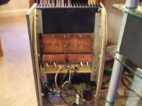
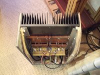
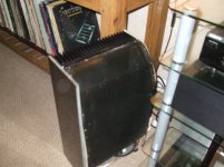
It is all in the build
twin+ cascode+duble jefets+34V rails+40X 10mU cap
But maybe this is one of the post that do qualify to be banished.
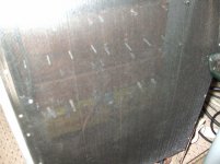
Sill case is prety cold as it has no inside realy I got same mesh that I was going to fit but never got around to it
twin+ cascode+duble jefets+34V rails+40X 10mU cap
But maybe this is one of the post that do qualify to be banished.
Sill case is prety cold as it has no inside realy I got same mesh that I was going to fit but never got around to it
Attachments
Last edited:
Great!
If you could double (parallel) the input Fets one could add even more output pairs. Maybe a complementary B2 output board...
Hmm. It's getting a bit tight in the middle there.
What's a B2 output board?
It's worth it.
ooops I meant complementary BA-2 output board
Do you mean paralleling up Q1 & Q2?
OK. I see what you mean regarding the BA-2.
Hmm. Need some pads..............
Someone else can do the monoblock. My brain is fried!
Thanks for the hard work. I wouldn't where to start.
I was trying to point out that putting four pairs of outputs on one heatsink may make it difficult to set the bias very high. Perhaps negating the advantages of using multiple pairs of outputs.
- Status
- This old topic is closed. If you want to reopen this topic, contact a moderator using the "Report Post" button.
- Home
- Amplifiers
- Pass Labs
- F5 Turbo is posted