Andy:
The timing for this could have been better, but diyaudio has announced that they will be offering certain HiFi2000 enclosures for sale in the US sometime soon. Two of the enclosures would be suitable for V2 and V3 F5 Turbos. For those of us in North America, this is very good news. Diyaudio is also offering to predrill and tap mounting holes on the heatsinks to their new universal mounting specification, which will make future swaps of boards in these amps very easy.
Is there any chance you might consider revising your V2/V3 output boards to conform to the diyaudio universal mounting specification? Doing so would be enormously helpful to those of us in North America who plan on sourcing HiFi2000 enclosures from diyaudio.com.
Just hopin'.
Regards,
Scott
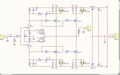
a single pair will give a maximum ClassA output power of P(ClA) = [2*0.8]^2 * 8ohms / 2 = 10W into 8r0.
If you fit a 2pr output stage the maximum ClassA output Power increases to 4times (P*2^2) the single pair. i.e. 40W
a 3pair stage will give 90W (*3^2)
This latter 3pr will require an output voltage of 0.8* 2 *3pr * 8ohms = 38.4Vpk
This will require operating supply rails of ~ +-42Vdc
Substitute 1pr or 2pr or 4pr into that formula to find Vpk for the alternative output arrangements.
sorry. i ment +/-42V it was a typo
")
Attachments

Last edited:
Spring clip, spring clamp, whatever holds a device in position with pressure.Spring?
Did i say that ?why 2 heatsinks in series work better than one?
201W will be one heck of a number for your heatsinks.........
2.4A x 42V x 2 = 201W
that seems like a good number for my heatsinks.......
Have you modeled them yet?
Andy:
The timing for this could have been better, but diyaudio has announced that they will be offering certain HiFi2000 enclosures for sale in the US sometime soon. Two of the enclosures would be suitable for V2 and V3 F5 Turbos. For those of us in North America, this is very good news. Diyaudio is also offering to predrill and tap mounting holes on the heatsinks to their new universal mounting specification, which will make future swaps of boards in these amps very easy.
Is there any chance you might consider revising your V2/V3 output boards to conform to the diyaudio universal mounting specification? Doing so would be enormously helpful to those of us in North America who plan on sourcing HiFi2000 enclosures from diyaudio.com.
Just hopin'.
Regards,
Scott
The DIYAudio spec is 40mm I believe but that's too close so they'd have to be 80mm centres I guess.
If there's a consensus on this I'm happy to layout an alternative board but with 4 MOSFET's per board that would make them pretty long.
Looks like I need to find and read the UMS.
From these comments it appears to me that the universal is not at all a universal standard.
Andrew,
UMS is here http://www.diyaudio.com/forums/imag...ersal/universal-mounting-specification-v2.pdf
Andy
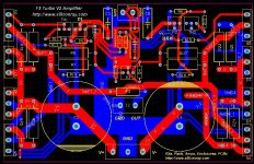
Finished the F5 Turbo V2 design, schematic and PCB posted. Could you help me to check whether there're mistakes? thanks
Planning to make in Black, 2oz gold pasted copper.
I am not sure what the law or policy is.
But SiliconRay is a commercial entity, and taking NP's designs and using them commercially probably is not proper.
I know other designs are "used" by third party commercial entities and sold elsewhere, but not by participants in this forum, AFAIK.
Perhaps a moderator or NP should comment??
Regards,
_-_-bear
Risking condemnation and being tarr'd and feathered, run out of town.
On the V3 type output boards, why are the power resistors "buried" inline with the mosfets? It seems to me that they should be slid out from that line, both for heat reasons and for heat reasons. Both of those reasons, and also by doing so larger resistors can be accommodated than the minimum size. Those resistors that use the flatpak plastic case (Vishay/Caddock) also require heatsinking, I'd have left ample space for that possibility, and used the maximum width of the board possible for larger format resistors.
On the V2 combo board, neat layout to the eye is nice, but as I was trying to convey early on, good looking and good performing are not always the same. Asymmetry is not something that needs to be avoided all the time. Here too, I have concerns about the resistor placement and layout for the larger ones. Also the pad size as I mentioned early on. Better to push the limits in size.
On both the V3 output board and the V2 board there is much dead space. PCB mfrs charge by the the area, not the layout... so I'd try to spread out the component layout, both from a heat point of view (these are GOING to run HOT) and the ease of service and construction point of view. On the V2 board I see some small resistors sandwiched tightly because the position of a header, C3 means that R11 is right there... sure, it will fit, but why so tight? (just one obvious easy to see example...)
The TPs position assumes that the final installation will provide easy access to the TPs from the "top" of the board. Not a good assumption. Probably they will not be accessible at all from the top, rather one will have to fish in from the top of the amp, which works out to be the side of the board. So, having them inline makes it easy to short them out with a meter probe. I'd have set them at what would be 45 degree angles looking down on the board, and added space from the Pots - the pots could be top or side adjust, which makes it easy enough for the screwdriver to slip off if side adjust again shorting the TPs (unless the TPs are socket type in which case you can't get to them from the side, so assume uninsulated pins) - the step spacing making it possible to get to the TPs from various angles.
Since these boards are going to be slapped on MAJOR LARGE heatsinks, usually standing vertically from the main chassis, there is not a whole lot of benefit from making the tightest layout using the smallest board possible. In fact there are deficits in terms of layout options and heat build up.
Making the boards have a larger long dimension, as long as it does not effect stability, is a BIG advantage because you need space to permit each mosfet to adequately flow heat to a region of the heatsink.
Folks who are using front to back heatsinks on a deep chassis, and using this sort of board are really only getting part of the heatsink value that they have paid for, because the heat is being generated only in the central portion. Yes the rest of the heatsink helps, especially once it has been cooking for a while, compared to a shorter extrusion, but it is none-the-less not as effective as wider spacing. So what's the loss in adding a few inches in length to this sort of layout if it buys better heat transfer and wider component spacing with fatter traces and bigger pads??
Looking cool and sexy by being compact and packed in, is a false design goal or aesthetic, imo.
One should de-rate ALL the components based on heat rise over 70F (whatever that is in C) ambient temperature. In summer conditions the environment around that board is going to get VERY HOT, reducing the effective wattage of all of the resistors. Me, I want max space and max air flow.
Count on designing from an ambient air temp of >100F (whatever that is in C?), add in the temp rise due to the circuit, and then you'll see why this is important.
Personally, I do not what to listen to a great amp and fans. Not if it is possible to NOT listen to fans. If it is a fan, the slower the fan, the higher the VOLUME and the lower the velocity of air, the better... but would rather not hear or have a fan full time.
If ur building right now - do NOT put ur small resistors flat to the board!! Make sure you put about 1-2mm or ~0.64" or so minimum clearance between the resistors and the board. More is better. Less clearance is worse.
I'd want more spacing resistor to resistor for the "small" wattage ones, again for heat purposes. If I had to build on these boards, I'd end up putting every other resistor high (a full extra resistor body diameter) off the board on it's leads to permit adequate air flow, not in-line at the same height. High - low - high - low - high - low ...etc.
My only other thought at the moment is "black"?? What sort of material is it? Black is usually a carbon based pigment which is not a particularly good insulator, albeit probably up in the MOhms, but still of some concern... also black will absorb heat from outside sources better... and there is heat to be absorbed being next to the heatsinks...
All of this may be nit picking, but maybe not given the heat that this amp will put out. Optimizing for heat may be important.
Oh, speaking of which, a good way to test heat is to pick up a cheapo non-contact thermometer. Great stuff for testing temps on electronics!
Please don't stone me?
_-_-bear
PS. Toecutter, I think you've done a great effort, please make sure that this message comes across...
Last edited:
PPS... someone mentioned copper being bright finished as not a good radiator of heat? Not sure about that at all, but if that is an issue there are a variety of chemical agents that can put a thin black finish on copper... of course of those agents create an insulative layer, maybe not so good... heh. Something to look into.
- Status
- This old topic is closed. If you want to reopen this topic, contact a moderator using the "Report Post" button.
- Home
- Amplifiers
- Pass Labs
- F5 Turbo Circuit Boards