
Hmmm, ZM posted a link
Typical him, you'll get used to it
ZM ; upper left corner
I think you mean this?
See pic.
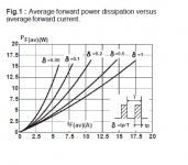
Ouch...than it's at 2,5 Amp forward, average, 50 % duty cycle, about 2,4 Watt...even more then I calculated... ?
Attachments
naah
just read what my Dutchie Whale is writing ......
you're having - what ? - 2A5 Iq
overall 8 diodes ( in two Graetzs ( btw. one Graetz bridge is having 4 of them - ook wiki if you don't read it )) ;
)) ;
conclusion - in each halfperiod you'll having half of 8 diodes conducting ...... that's translating as 2A5 burden on all 8 diodes in full periode
so 1A25/4 diodes is ........ 0,3125A
even if I erred 100% , say that that plate will be warm
just read what my Dutchie Whale is writing ......
you're having - what ? - 2A5 Iq
overall 8 diodes ( in two Graetzs ( btw. one Graetz bridge is having 4 of them - ook wiki if you don't read it
)) ;conclusion - in each halfperiod you'll having half of 8 diodes conducting ...... that's translating as 2A5 burden on all 8 diodes in full periode
so 1A25/4 diodes is ........ 0,3125A
even if I erred 100% , say that that plate will be warm
Attachments

Last edited:
naah
so 1A25/4 diodes is ........ 0,3125A
Hi Zen Mod, this last one I don't understand...
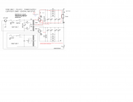
See pic.
Every conducting diode is seeing the 2.5 A ? Ok, maybe x 0.707 or something because it's a sinewave...but why divide it by four?
Attachments
Last edited:
I may be wrong but here goes. Of the 4 diodes pairs 2 conduct pos. and 2 neg. one pair each direction 1/2 of the cycle thus produce 2.5 a / 4 pairs of diodes or 1.25a /4 there it is Zen Mod answer or at least what I understand . The drawing shows a 4 diode bridge when we have an 8 diode bridge ( each to-247 is a pair) . Hope that helps.

I have built two discret bridges per channel using on semiconductor's mur3020wt diodes. They are slightly warmer side with bias of 0.6A/ device. Used small heatsink. As per datasheet it dissipates 1W for 2A forward current. Here diodes are conducting less than ampere per cycle, so dissipation is less than 0.4W / diode.
Last edited:
Very wrong also.
At 50/60Hz mains, the caps are charged 100/120 times a second.
But each charge period does not last 1/100th or 1/120th of a second.
Charge current will only flow when charging voltage exceeds cap voltage level.
So only a tiny portion of the sinus slope is available for restocking the lytics.
If you calculate the ripple level for the smoothing cap number per rail and the bias level you have chosen, the lowest rail voltage level follows.
The sinus slope then tells at which point the diodes start conducting, from there till the sinus peak and back is the charging period.
Average charge current x charge period x 100 (or 120) ~ bias level (remember : VxI = VA ~ W = Joule per second)
For the MUR3020 : 1A x 0.6Vf x 1s < 10A x 0.92Vf x 0.1s
Last edited:
it will be warm
Me idiot, when the sun shines and it's warm, I believe it's summer. (half the time)
- Status
- This old topic is closed. If you want to reopen this topic, contact a moderator using the "Report Post" button.
- Home
- Amplifiers
- Pass Labs
- F5 Turbo Circuit Boards