sorry
Hi mrdrewk
Sorry I can't really help here. These questions you have are amp-specific, and I don't know this one. (just plugged in my F4 )
)
The arrows may indicate "something"—bias / offset up for example? Just guessing!
Somebody who is accustomed to F5t has to chime in...
(PS: If you can, use the "manage attachments" function under "additional options", below. It is available if you reply through the "Post Reply" Button, or by clicking "go advanced" if you started with a quick reply. The pics then come as thumbnails instead of being embedded in the post)
Hi mrdrewk
Sorry I can't really help here. These questions you have are amp-specific, and I don't know this one. (just plugged in my F4
)The arrows may indicate "something"—bias / offset up for example? Just guessing!
Somebody who is accustomed to F5t has to chime in...
(PS: If you can, use the "manage attachments" function under "additional options", below. It is available if you reply through the "Post Reply" Button, or by clicking "go advanced" if you started with a quick reply. The pics then come as thumbnails instead of being embedded in the post)
thank you very much @myleftear! It has been exciting to pull these pieces together.
On the P1 and P2 trimpots, 6L6 has arrows on them that he drew on with a pen. What's that for? Something I should measure before stuffing and soldering them down?
Stuffing the N and P channel boards. On the "BOM for DIYaudio F5 Turbo"
mentions TH1 = 4.7Kohm NTC for BOTH N channel and P channel boards. The "F-5t N Channel O/P" board only has a TH2. That's a typo right? There's a thermistor (?) on both P channel and both N channel boards: four in total.?
Also, only R11, and TH1, on P channel boards say
"use only on 1 P ch board pr channel"
R12 and TH1 (TH2?), on N channel boards say
"use only on 1 N ch board pr channel"
Each channel, Left and Right, have one P and one N channel boards. So, that's only one P channel board and one N channel board per Left and Right channel. So all boards get all of them?
Let me know if you see any other glaring mistakes on these boards - thank you very much!
P-channel board
N-channel board
Check the build guide and see pics of original vanilla F5. two TH per sink and one per output board Else it might get hot in your house... I would not solder these until fets are mounted/you know how long legs you need. But prolly no bigge if u did.
Yes. Push pull means one N and P per channel/sink.
Use sinks on the cascode bipolar fets. You can ommit thermal pads, but then the sinks will be live. Prolly no big problem, just watch your fingers.
Arrows on pots is just a time saving measure to let one know if turning this or that way increases or decreases resistance, in most cases bias or offset.
Whether there are mistakes or not made on your boards, I cannot say. Need close look for that. Plus I never built it. Someone else might be equipped to help you there. But if it doesn’t catch fire or blow up during power up, you probably did it right. Hehe.
Cheers,
A
Last edited:
Q7, Q8
Seeing that the F5 amp appeared way back in 2012-3? and seeing the handwriting on the wall I’ve started “collecting/hoarding” parts to enable me to be able to build several, if not all, of the various permutations of the F5 amps well into the future along with a few other favorites from Mr. Pass.
Anyways stumbled into this while working off the F5T-V3, BOM (for the front end boards, mono’s, cascoded version) while hound dogging around for parts Q7 and Q8.
Naturally Parts Q7_aka Toshiba 2SC4793 and Q8_aka Toshiba 2SA1837 are both “Obsolete & Not Available.”
Per The Man…“The choice of Q7 and Q8 is not critical – for the most part they merely need not to break. Here is one of the few places I prefer Bipolars to Fets, as they will be less inclined toward the aforementioned parasitics.”
Also noticed a LTB, (Last Time Buy) Option sheet Toshiba sent to Mouser dated November 30, 2016 that both Q7 & Q8 have a Toshiba replacement part(s) number? along with a few more of interest. Bit Huge but here’s the link if interested …https://www.mouser.com/PCN/Toshiba_America_Electronic_Components_Inc_EOL_X35___MOUSER_11302016.pdf
So supposedly, per Toshiba for Q7 a TTC011B,Q(S is a replacement and for Q8 a TTA006B, Q(S. may work?
Sooooo my question is has anybody already tried this replacement or compared the spec. sheets or ??? have I just missed something obvious here…If so it’s not the first time and surely won’t be the last.
Found 53 of the bipolar TTA006B’s in my parts debacle? and ordered 50 of the TTC011B’s from T.M.E. Poland. Time to dig out the equip. and look up the spec. sheets and see if these two play well together.
Thanks in advance y’all…RatBoy
I have enough of those bipolars for two front ends. But guess that doesn’t get you very far if you are building monoblocks. Give me a chime if you want me to dig them up and send them over the Atlantic.
Used parts, reliable source, but haven’t tested them.
That said, I think you safely can use other parts still for sale as long as they have roughly the same values. If 6L6 or ZM don’t chime in, maybe you could PM, they amongst other greedy boyz will prolly know what to choose, but you seem experienced enough so I guess the ones you found are probably good enough.
Cheers.
Andy
Folks:
Okay, I'm officially freaking out. Something scary is happening with one of my F5T V3 amps. A brief history: one of the two monoblocks released magic smoke months ago, apparently when a 7-year old Keratherm Red insulator failed. I replaced all of the insulators on that monoblock with AI203 ceramic pads and Kryonaut thermal paste. All of the active parts on that amp were also replaced, as were a few passive parts. That monoblock now works just fine.
As a prophylactic measure, I made similar improvements to the other monoblock (replaced insulators and upgraded some resistors). I'm now trying to rebias that amp. With P1 and P2 (the 5k pots) each dialed to below 5R, I'm reading about 12mV Iq across the test points on the P channel side of the amp and 0mV Iq across the test points on the N channel side. You'd think I was ready to set the bias, except I'm reading about 45 VDC offset at the output. Rail voltages are +-46.1 VDC.
What could have caused this?
Thanks,
Scott
Strange, but so interesting! Did you unsolder any of the dc wires from the boards in the process? Any other changes from before apart from replacing pads/paste? Could inverted wires be the cause? Excited about the solution here. Pics?
If you unsoldered diodes or fets, have you checked if they got mixed up? Unlikely but...
PS: are both rail wires from PSU well connected to PSU? Long shot but, if rails are 45v whqt you are experiencing could be one dead rail wire/pad lift/poor connection. Longshot that too prolly..
Andy
If you unsoldered diodes or fets, have you checked if they got mixed up? Unlikely but...
PS: are both rail wires from PSU well connected to PSU? Long shot but, if rails are 45v whqt you are experiencing could be one dead rail wire/pad lift/poor connection. Longshot that too prolly..
Andy
Last edited:
Andy (& Co.):
My last post was incomplete; I neglected to mention that one of the N channel MOSFETS in the amp failed when I tried to bias it a few days ago. I replaced all of the N channel MOSFETs (and the MUR3020 diodes for good measure) yesterday. I looked at but did not test the P channel MOSFETs; there was no evidence of a problem on that side.
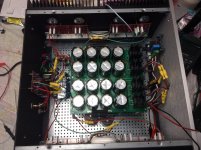
I doubt the attached photo will help much, but the DC power lines are correctly attached. I'll verify that the N-channel MOSFETs and diodes are where they're supposed to be, but that isn't likely to be the issue.
Regards,
Scott
My last post was incomplete; I neglected to mention that one of the N channel MOSFETS in the amp failed when I tried to bias it a few days ago. I replaced all of the N channel MOSFETs (and the MUR3020 diodes for good measure) yesterday. I looked at but did not test the P channel MOSFETs; there was no evidence of a problem on that side.
I doubt the attached photo will help much, but the DC power lines are correctly attached. I'll verify that the N-channel MOSFETs and diodes are where they're supposed to be, but that isn't likely to be the issue.
Regards,
Scott
Attachments
...I'm reading about 12mV Iq across the test points on the P channel side of the amp and 0mV Iq across the test points on the N channel side. You'd think I was ready to set the bias, except I'm reading about 45 VDC offset at the output...
That would be expected, the P side has started to conduct, the N side has not. First, plug in your dim bulb tester, then twiddle the N side pot until it starts conducting, the voltage on the output will begin to drop; remove the dim bulb tester and carry on with the bias procedure.
Folks:
Okay, I'm officially freaking out. Something scary is happening with one of my F5T V3 amps. A brief history: one of the two monoblocks released magic smoke months ago, apparently when a 7-year old Keratherm Red insulator failed. I replaced all of the insulators on that monoblock with AI203 ceramic pads and Kryonaut thermal paste. All of the active parts on that amp were also replaced, as were a few passive parts. That monoblock now works just fine.
As a prophylactic measure, I made similar improvements to the other monoblock (replaced insulators and upgraded some resistors). I'm now trying to rebias that amp. With P1 and P2 (the 5k pots) each dialed to below 5R, I'm reading about 12mV Iq across the test points on the P channel side of the amp and 0mV Iq across the test points on the N channel side. You'd think I was ready to set the bias, except I'm reading about 45 VDC offset at the output. Rail voltages are +-46.1 VDC.
What could have caused this?
Thanks,
Scott
Just a thought: what if your issue isn’t Keratherm related at all? There are stories about these blowing up.
I see you have optional C’s installed. What is your gate resistance?
And: what was your bias prior to the first blow up? Any chance the diodes started conducting? New heating oven, new apartment/house and hotter room temps?
And just to see if I understand you correctly:
Did you replace the Keratherms before or after the N-channel blew?
The answer might lead the way to the solution.
Andy
Folks:
Okay, let me try to answer everyone in one fell swoop:
Before the second monoblock blew, its bias was set at +0.331 / -0.332 VDC and offset was under 2.4 mV. That amp had been working fine for years.
The power supply is properly delivering DC to both the P- and N-channel O/P boards. Rail voltages are +45.7 VDC and -46.7 VDC (P- and N-sides, naturally).
I don't have a 100W incandescent bulb on hand. With a 60W bulb, my dim bulb tester lights bright and then dims considerably but does not go completely off.
Resistance across P1 is currently set at 0R5 and across P2 it is 2R1.
Voltage across R5 is steady at 4.9 mV, across R6 it is 79.7 (but very slowly drops).
Voltage across R3 is 3.389 V, across R4 it is 3.080 V.
Offset is 45.1 VDC.
As noted above, after the first monoblock was repaired, I decided to make similar improvements to the second amp (which was working fine). So the Keratherms were replaced by the ceramic insulators, some resistors were upgraded (from 0.25 and 0.5W to 1W) and small value anti-oscillation caps were placed in parallel with R3 and R4. The N-channel MOSFETs blew on the second amp post-repairs during the bias procedure. They (and the MUR3020 diodes) were replaced with a matched quartet of IRFP240.
My working assumption is that AudioSan is correct and the P-channel MOSFETs are defective; without removing those MOSFETs from the amp, I tested the drain and source pins on each of the four P MOSFETs with my DMM in diode mode and got a reading of 0 V.
I'm clearly no engineer and everyone's guidance is very much appreciated. What do you suggest?
Thanks in advance for the help,
Scott
- Home
- Amplifiers
- Pass Labs
- F5 Turbo Builders Thread