Thanks 6L6!
I biased it up to 300mV with no shorting plug using 2.2k ohm resistors for R5 and R6.'
The larger values make the adjustment a bit more touchy.
There is a lot more bias possible with this arrangement, that I am not going to need.
The thermistors kicked in quickly, and dropped the bias to 285.
I will let it cook for a while.
It settled down to 268 mV across 3 boards. One board was 274, using the cheapest/dodgiest meter I have. 10% drop from cold.
Tomorrow, assembling the other channel. It only needs mechanical work -- screw it together. And the 2.2K ohm resistor swap All boards have spades and terminal strips and wire is in place,.
Will confirm that DC offset is stable with/without shorting plugs.
Tomorrow, assembling the other channel. It only needs mechanical work -- screw it together. And the 2.2K ohm resistor swap All boards have spades and terminal strips and wire is in place,.
Will confirm that DC offset is stable with/without shorting plugs.
Last edited:
It settled down to 268 mV across 3 boards. One board was 274, using the cheapest/dodgiest meter I have. 10% drop from cold.
Tomorrow, assembling the other channel. It only needs mechanical work -- screw it together. And the 2.2K ohm resistor swap All boards have spades and terminal strips and wire is in place,.
Will confirm that DC offset is stable with/without shorting plugs.
Congratulations!!!! It’s been a long road for you to get this far. I have my F5 monos playing right now. Classical music, which is something I like to do early on Sunday mornings.
Yes. Just working on the rest now. I was going to thank everyone for their help when I could show a fully working amp, but I can do that sooner too....
THANKS TO ALL FOR HELPING!!
There are too many to mention.
I certainly could not have got this far without the help of the very patient people on this site.
BTW: DC offset is stable with/without shorting plugs!!!. Turns out that when you wire the boards *in parallel* it's like putting two amps in a single chassis -- you need anti-oscillation caps for each board.
Thank you! That is very kind of you to say.
Both channels now show the same DC offset shorting plugs in or shorting plugs out, I think it is basically done....
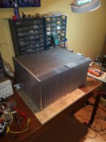
43.3 deg C 21.5 ambient, biased at about 290 mV, rails at 36.6 volts, about 86 WPC peak Class A power.
Can easily bias higher, but in the summer those 30 degree C days will push the heatsinking to the limit and I've got no A/C.
I guess the only thing to do now, is let it cook for a couple hours, then rebias both sides and close it up.
THANKS AGAIN TO ALL!!!!
Both channels now show the same DC offset shorting plugs in or shorting plugs out, I think it is basically done....
43.3 deg C 21.5 ambient, biased at about 290 mV, rails at 36.6 volts, about 86 WPC peak Class A power.
Can easily bias higher, but in the summer those 30 degree C days will push the heatsinking to the limit and I've got no A/C.
I guess the only thing to do now, is let it cook for a couple hours, then rebias both sides and close it up.
THANKS AGAIN TO ALL!!!!
Thansks Thompsontechs!
I've blown it up so many times, I can almost call myself a smoke eater....
But give me a chance, the lids still not on it.....wait, what am I thinking, I've blown it up with the lid on too...
I've been really lucky and the stuff I did wrong never blew anything major... yet! I did smoke a couple resistors in the SLB when I had something connected wrong.
**** happens, it's all part of the process of learning. When I wasn't sure, I tried asking someone here, if it wasn't for that I know I would have had to the pin on the Kitty.
")
Yes, it is learning -- the hard way.
I've ordered a wooden dolly to help move it around. I'm not so young anymore -- It's really heavy. It is coming on Tuesday -- I will listen to it then.
This has been one big weekend for the build, so I am going to quit work on it now. It is cooking with the lid on. Both channels are below 4 mV DC offset so far. I am thinking of measuring THD+noise at some point. Perhaps tomorrow
I'm wondering if replacing the 5K trimmers with 2.5K would be a good idea in this build?
Biasing would not be so touchy. Does anyone know which trimmers have the least play?
Attachments
F-5T v3 mono
I completed boards for my monoblocks and i'm wondering about :
Thanks in advance.
I completed boards for my monoblocks and i'm wondering about :
- R11,R12 - these resistors are mentioned only for P1 and N1 boards. Should i add it also in P2,N2 - or it's fine just as it is ?
- C1x,C2x are only on P1 and N1 also. I know that this caps are optional in general but should i add them also on P2, N2 ?
Thanks in advance.
Bias will be touchy no matter what. 4mV is outstanding!
Let it cook for a day, re-check bias and offset to make sure noting has drifted, adjust if required, and then let it sing!
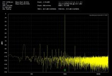
Awesome!!! I had a bit of a scare.... the THD testing on the right channel did not show any output at all.... turns out the rca was shorted with the smallest of solder bridges.
After fixing that, here are the distortion figures I get using the QA400. I know, not quite at 1 watt output, but check the SNR is different between the two channels.
I wanted to measure the effect of having snubbers on the diode bridge in real life.
I know both pics say Left channel, but the file names identify the correct channels...... the Left channel has a LOT better SNR. It has the resistor/cap snubbers on the diode bridge. It is also biased a little higher... 5mv or so? But I am guessing the reason is the snubbers, as the noise that dropped is at mains frequency and multiples.
These are the teabag power supplies. I will be adding the caps and resistors to the diode bridge on the Right Channel for sure.
There are no snubbers on the power transformer at this time.
THANKS AGAIN. THIS HAS BEEN AN AMAZING BUILD FOR ME BECAUSE OF YOU GUYS!!! I'd never have gotten this far without your help.
Attachments

Not quasimodo. That's the next step. I had it in once, but realized it should probably be built from X rated caps, so I removed it. The snubbers I'm talking about are the standard resistor/cap across each diode found on the Teabag boards to sink the switching noise of the diodes in the bridge.
I'm going to leave the bias, fix the diode bridge and retest. Just to take the difference in bias out of the picture, as higher bias seems to be a bit better too. After letting the real left channel rise further, I measured under 0.01% THD...0.008 it was -- and at very low power.
Bear in mind that these figures are taken at *less than 1V output* over an 8 ohm load. To get that load I wired 8 of the 1 ohm Fukushima resistors together, so it's an accurate 8 ohm load. The signal to noise ratio will be below -90 db at 1 watt output ( 2.83 volts ). The power here is near a tenth of that... this is a very very quiet amp.
It *does* have a hum breaking resistor on the Front end boards, and it is true dual mono -- only the power cord is shared.
- Home
- Amplifiers
- Pass Labs
- F5 Turbo Builders Thread